linuxrob
-
Posts
346 -
Joined
-
Last visited
Content Type
Profiles
Forums
Events
Store
Gallery
Community Map
Everything posted by linuxrob
-

Heated grips or heated gloves?
linuxrob replied to S-Westerly's topic in Clothing, Luggage, Accessories and Security
This guy i follow on YouTube has done a few vids on this topic. think this is his latest I would like some heated gloves just so i can stay warm from the house to bike etc. Use handlebar muffs and cheap Chinese heated grips on the GS125 in winter. palms are toasty and the muffs help keep the breeze off. On a faster bike this would not be as effective. The grips i got a few years ago still work but now the price is about 3 times the £2.99 i paid then. -
Can i nominate @Mickly
-
LED lights by there very nature will give more bang for you buck so to speak and yes a lot less load. Already have LED indicators (with an led compatible flasher), tail, stop and pilot light. The clock lamps are all LED as std on the K4 Bandit.. LED headlamps are OK with a matching reflector and lens arrangement. There are so, so many LED headlight "bulb" shapes, to get a bulb to work with a good and legal (safe) beam pattern will be the challenge Most of teh time you will get a glarey blob of light without the cut off on a dip.. Also the colour temperature of the light. 4500K is about right anything above i.e 5000-6000K will be too bluish - white. Always though an LED retrofired was an MOT fail? On single headlight naked bikes an aftermarket full unit should work well but to mod an excising unit designed for a filament bulb is almost impossible. A final point is the heat issue, not from the LED chip but from the driver circuit to get the chip to draw the right amount of current to give its rated light output. It does this by regulating the voltage/current as automotive battery voltages change with load and charge. excess power is wasted as heat so a heat sink is required to extend the life of the unit. Sorry for the waffle, but when i get started i find it hard to shut up Rob
-
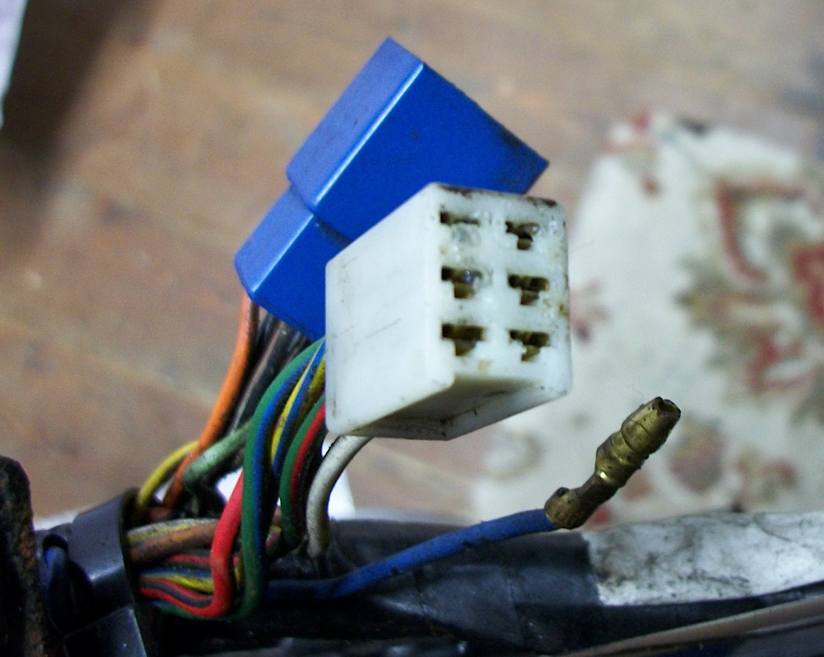
@Mr Fro. Thanks. The new Negative wires are indeed ran back to the main spine of the frame, the old PAIRS valve mount post actually. With all my bikes i link a few frame earth point together for a good solid return (share the load so to speak). I would love bike builders to run dedicated earths in the loom fro all circuits other than starter stuff. Never liked the thought of a steel frame carrying current, the way i was taught it would promote corrosion. You know that's a great idea. if i got a 5 pin relay i could, or just add another normally closed relay to the circuit. Wire it so when the starter button was pressed energising the start relay (black and yellow) that headlamp relay dropped out for cranking and back in again when the button was released. Thanks for the input

-
Annoying that everything "automotive" has a higher spec than our Japanese motorcycle equivalent.
-
Swiss Tony??????
-
I am so glad it is of use. I look forward to reading about it. GSX600F "teapot"? The Bandit uses HB4 for low beam and HB3 for High beam. Dip is the low bulb only, high beam just adds the high beam bulb. If the new H7 bulb you are using draws even more current (higher wattage) the voltage to it will drop more with the std small wires on your bike. Here are the links for the bits i used. Waterproof relays https://www.ebay.co.uk/itm/4PIN-12V-40A-Automobile-Relay-Waterproof-Integrated-Wire-Relay/114512386713?ssPageName=STRK%3AMEBIDX%3AIT&_trksid=p2057872.m2749.l2649 Wire https://www.ebay.co.uk/itm/Automotive-Auto-Cable-Wire-Wiring-12v-For-all-Vehicle-Applications-All-Sizes/124224780510?ssPageName=STRK%3AMEBIDX%3AIT&var=425078768022&_trksid=p2057872.m2749.l2649 4 way fuse box, this uses the same small blade fuses the bandit has. https://www.ebay.co.uk/itm/4-Way-Blade-Fuse-Box-Holder-with-LED-Warning-Light-Kit-for-Car-Boat-12V-24V-UK/203018362981?ssPageName=STRK%3AMEBIDX%3AIT&_trksid=p2057872.m2749.l2649 you may want to find new H7 and H1 connectors with larger gauge wires as I did with the HB4 and HB3 ones. the std ones should be ok as you will only use a very short length of original wire. I replaced mine to be 100% sure. I am sure that the K6 and above bandits use thicker wires i the headlamp circuit but they will only be just good enough. Regards Rob B
-
I nearly didn't. Will fine tune the aim of the beams before i put the fairing panels back on as i can get to all 3 bolts. As it was i did not feel safe at night with the way the Std setup was. I feel a YouTube slide show coming on!
-
thanks Stu, Will mod my coils to run of relays too as i did on my Z500
-
Thanks all for the encouraging words. I love doing all this and hope to help and inspire others to do work on their machines. Hope to get the oil heater on tomorrow in the shed and do some more. After this mod will be doing the fork oil change, 4 years since have flown. Want to try hydraulic oil this time. Roll on spring.
-
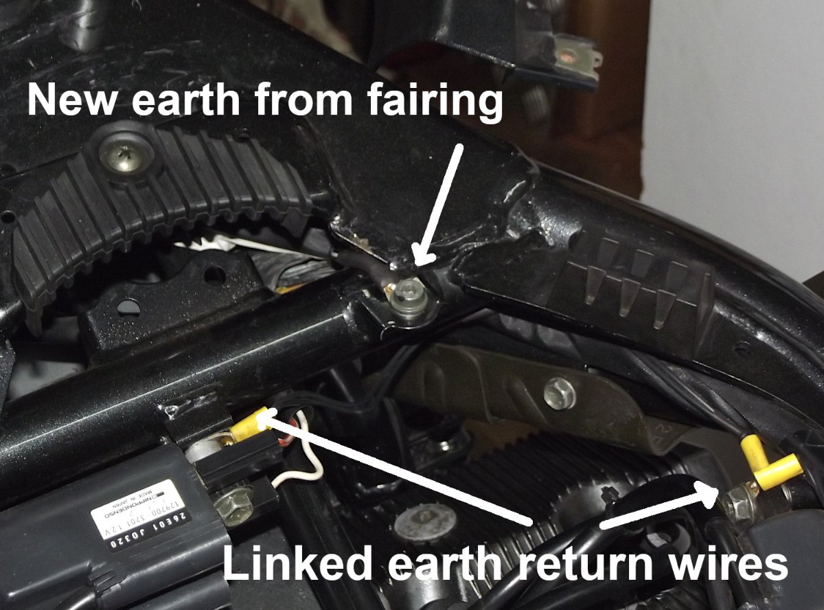
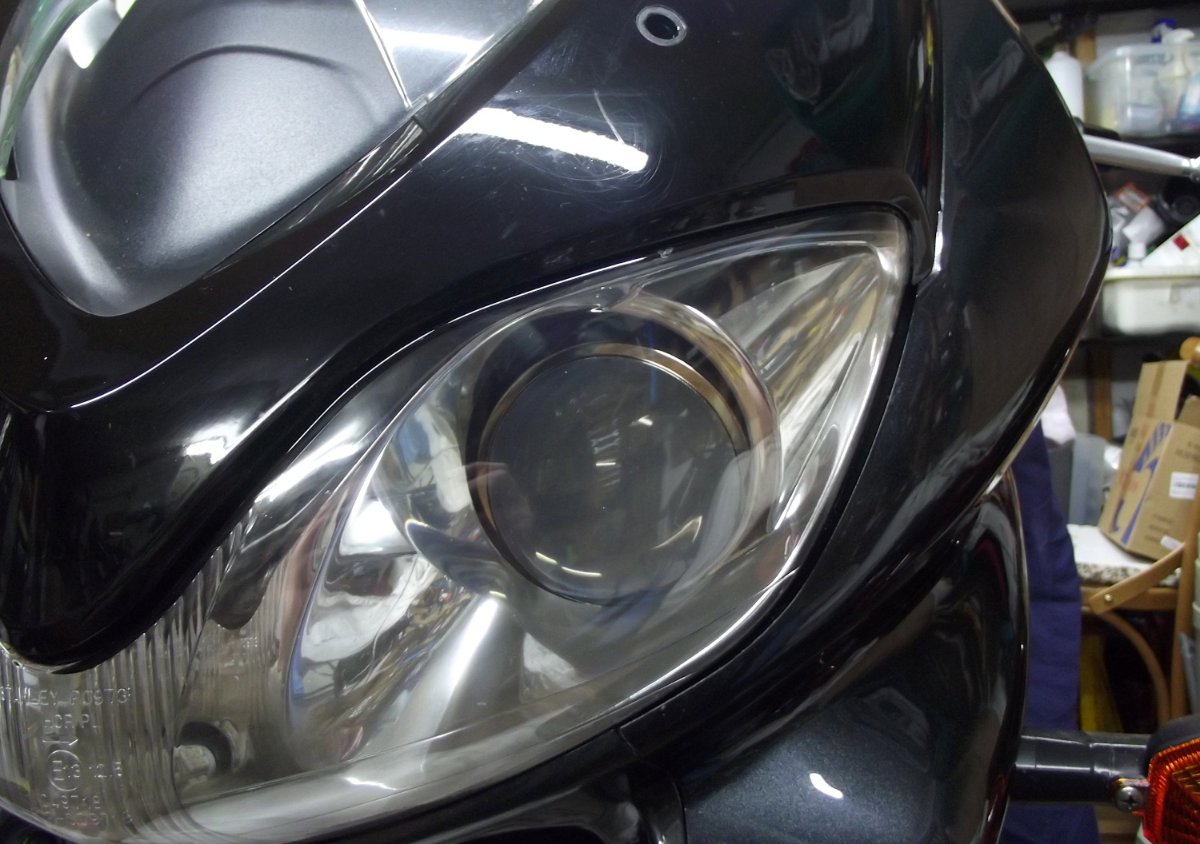
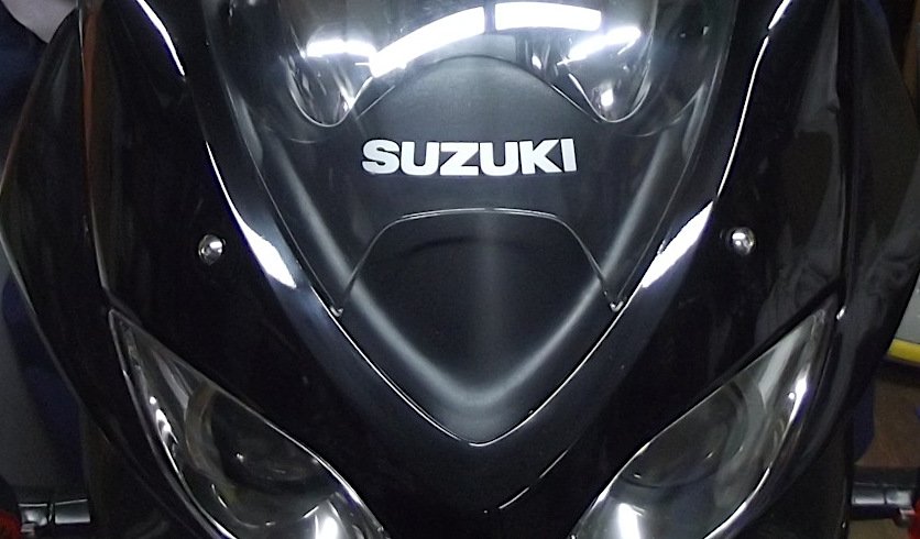
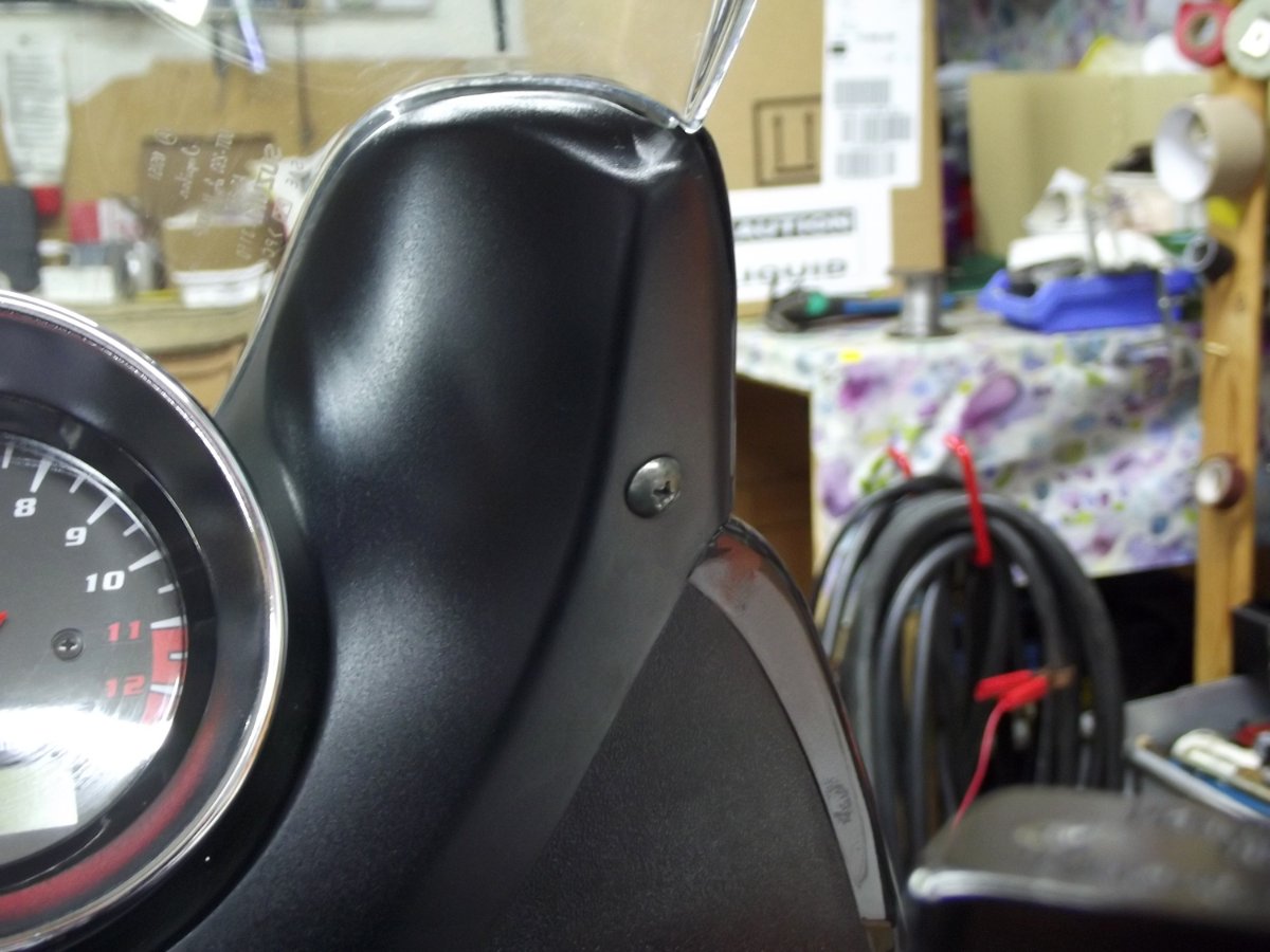
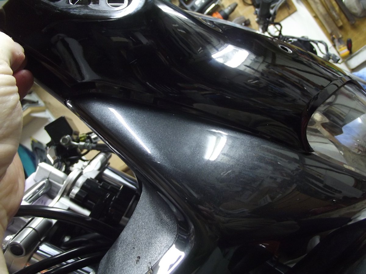
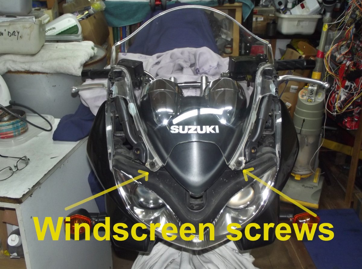
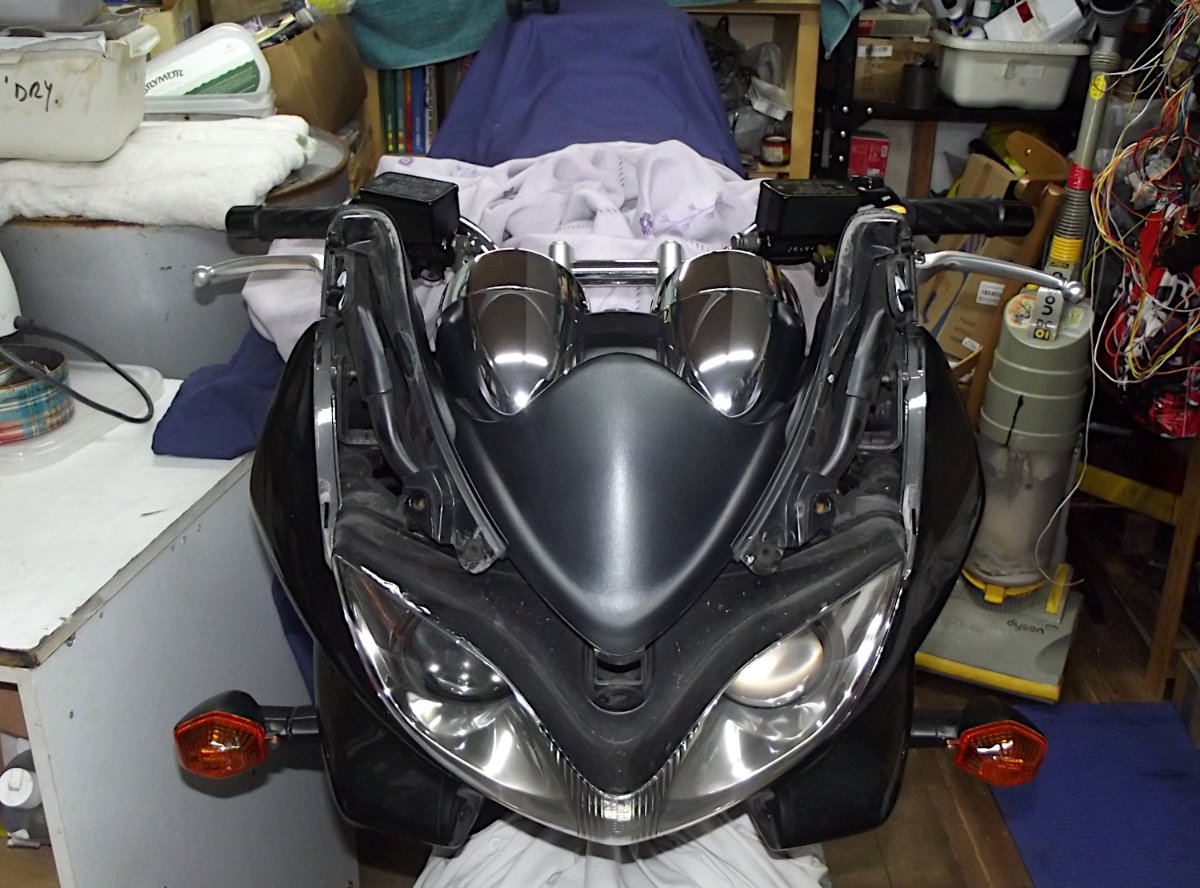
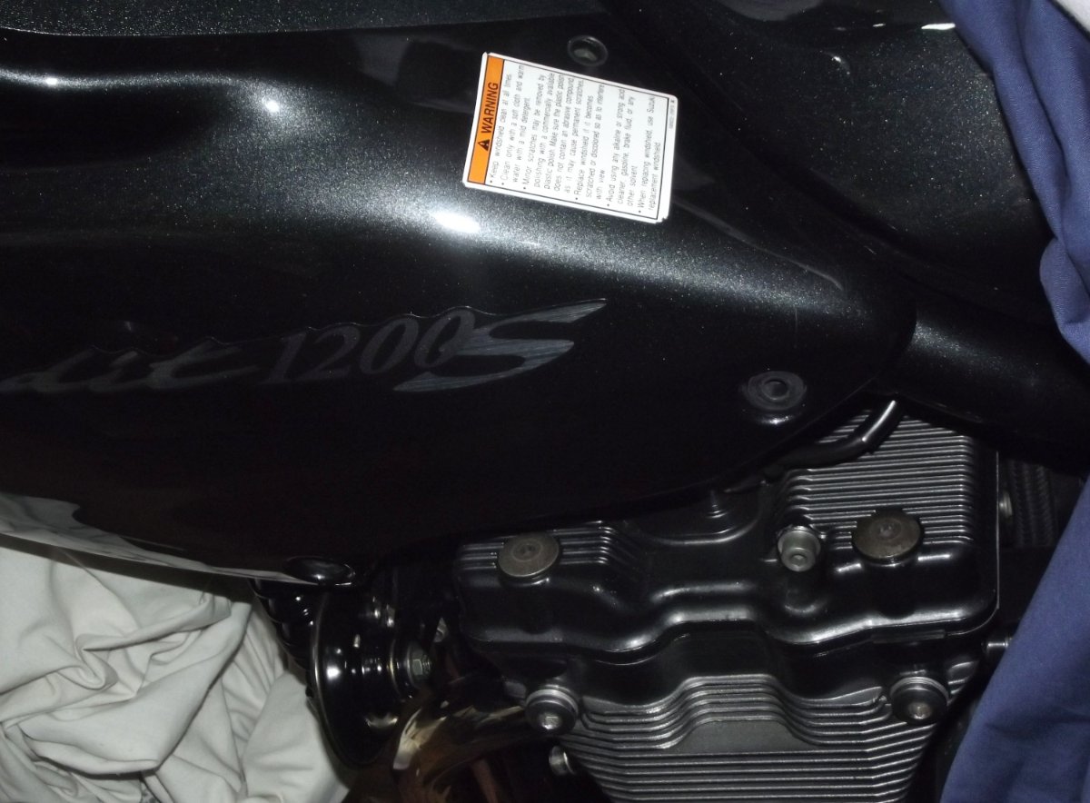
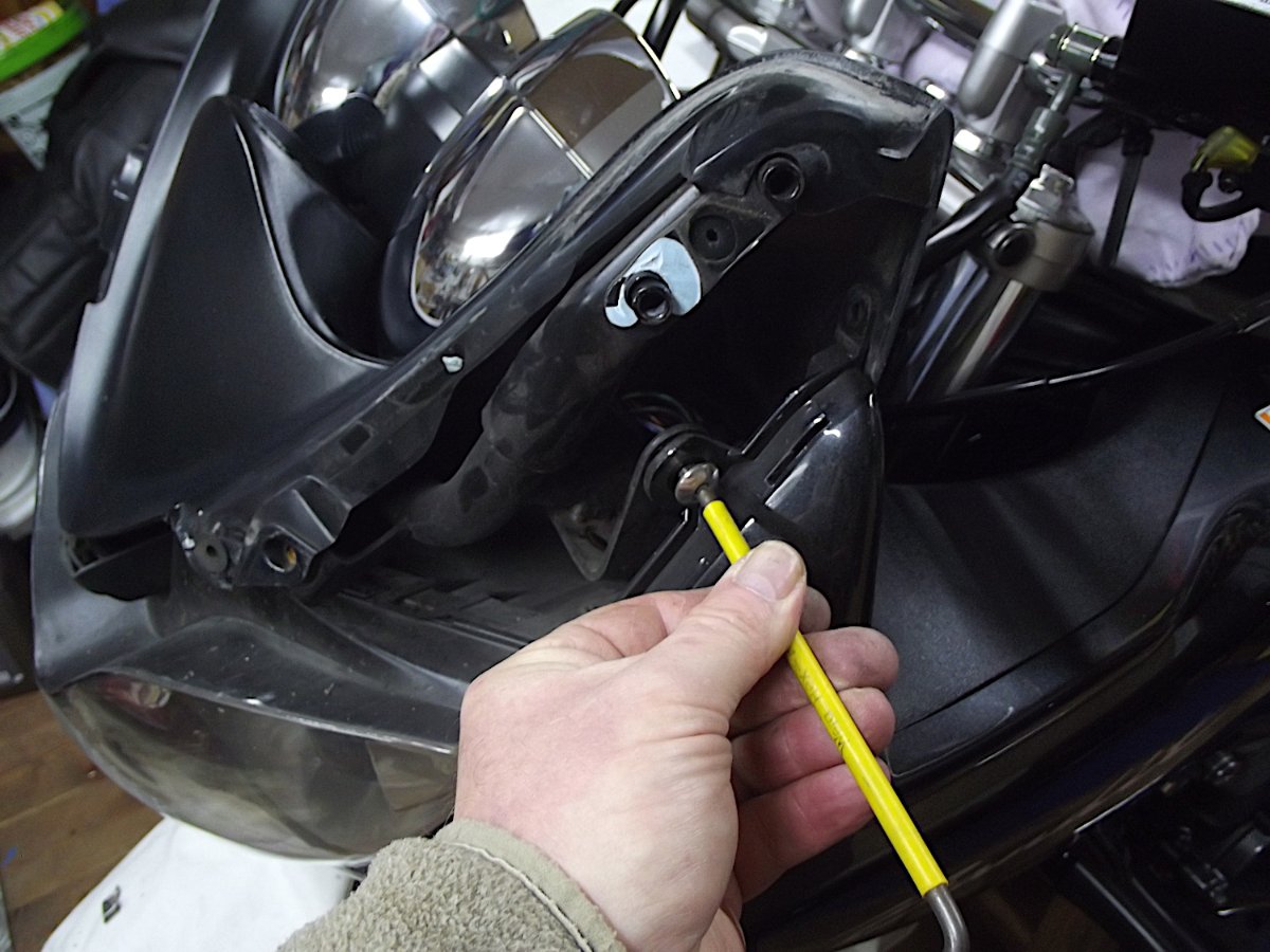
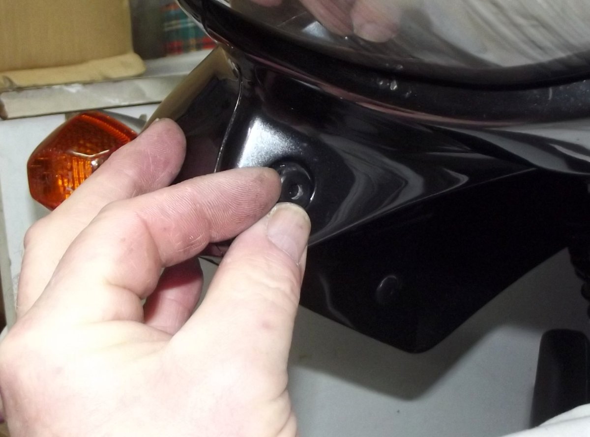
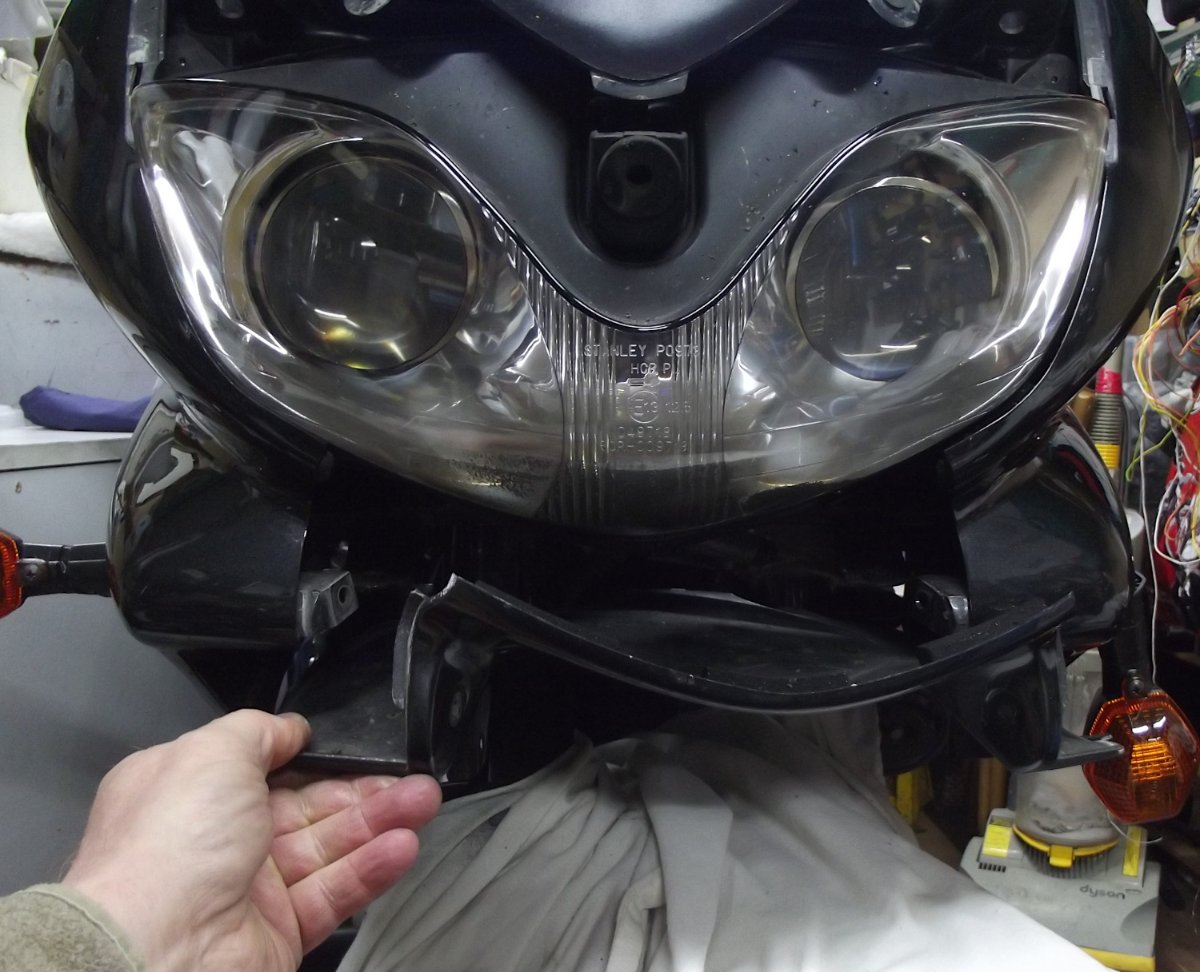
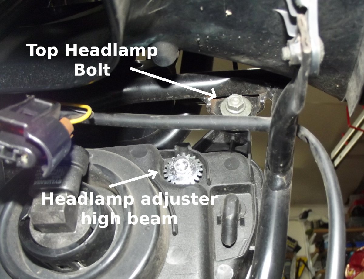
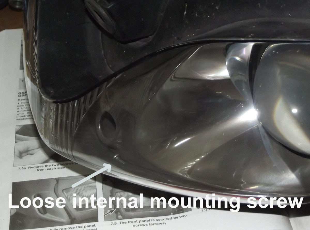
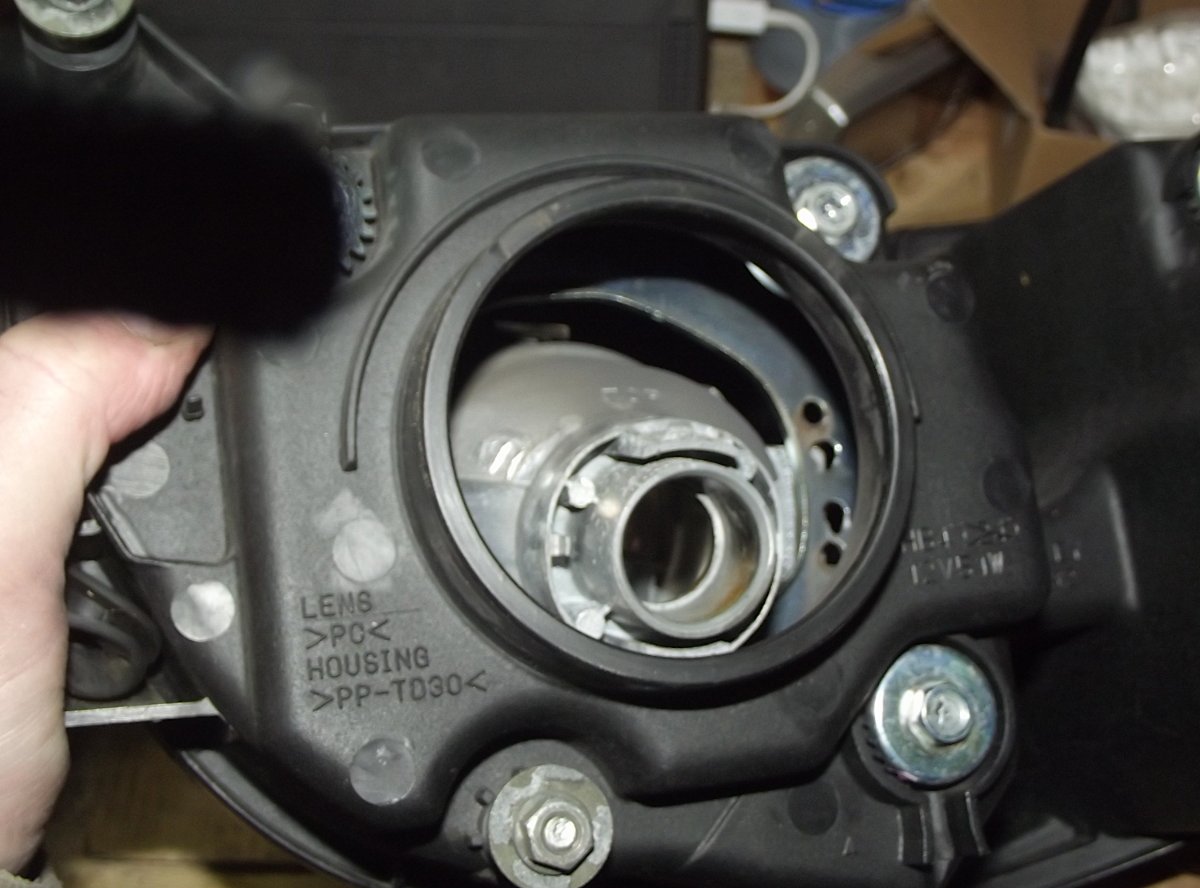
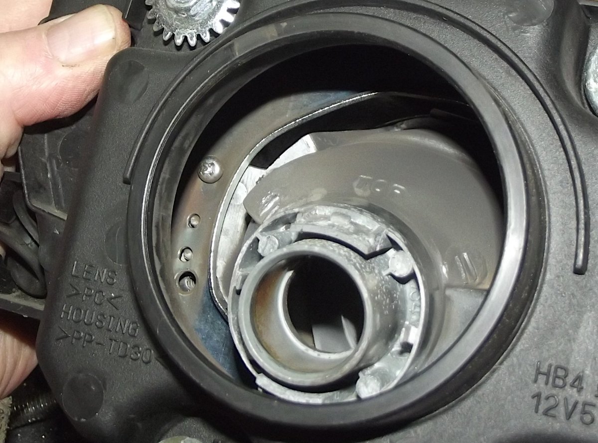
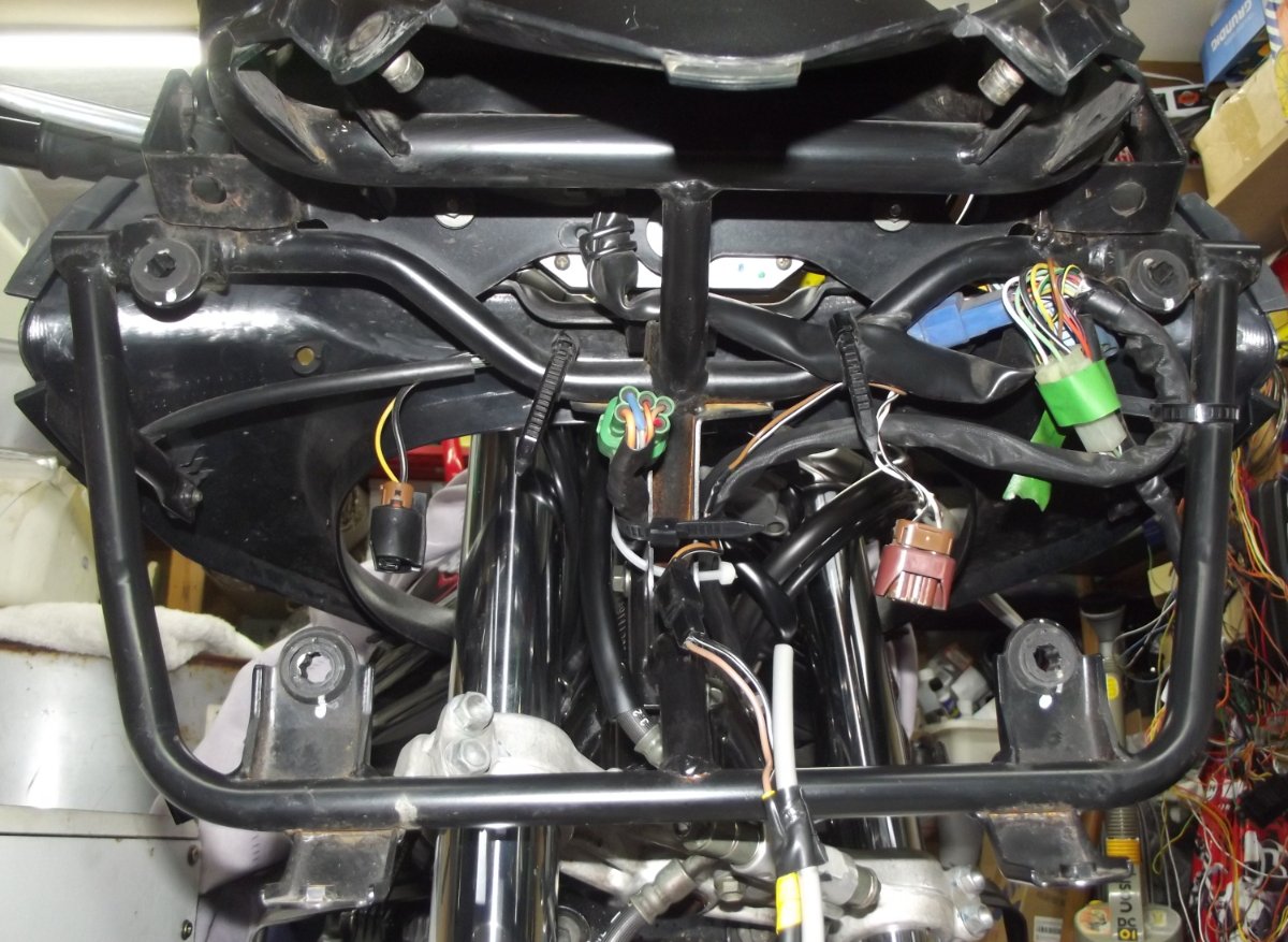
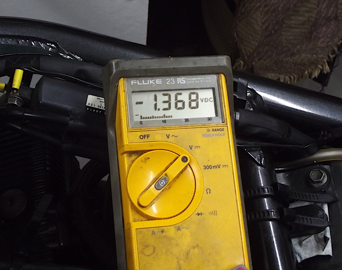
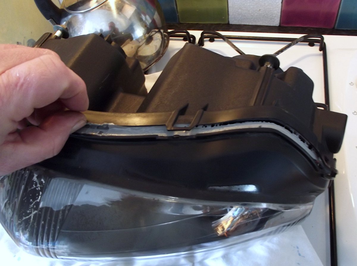
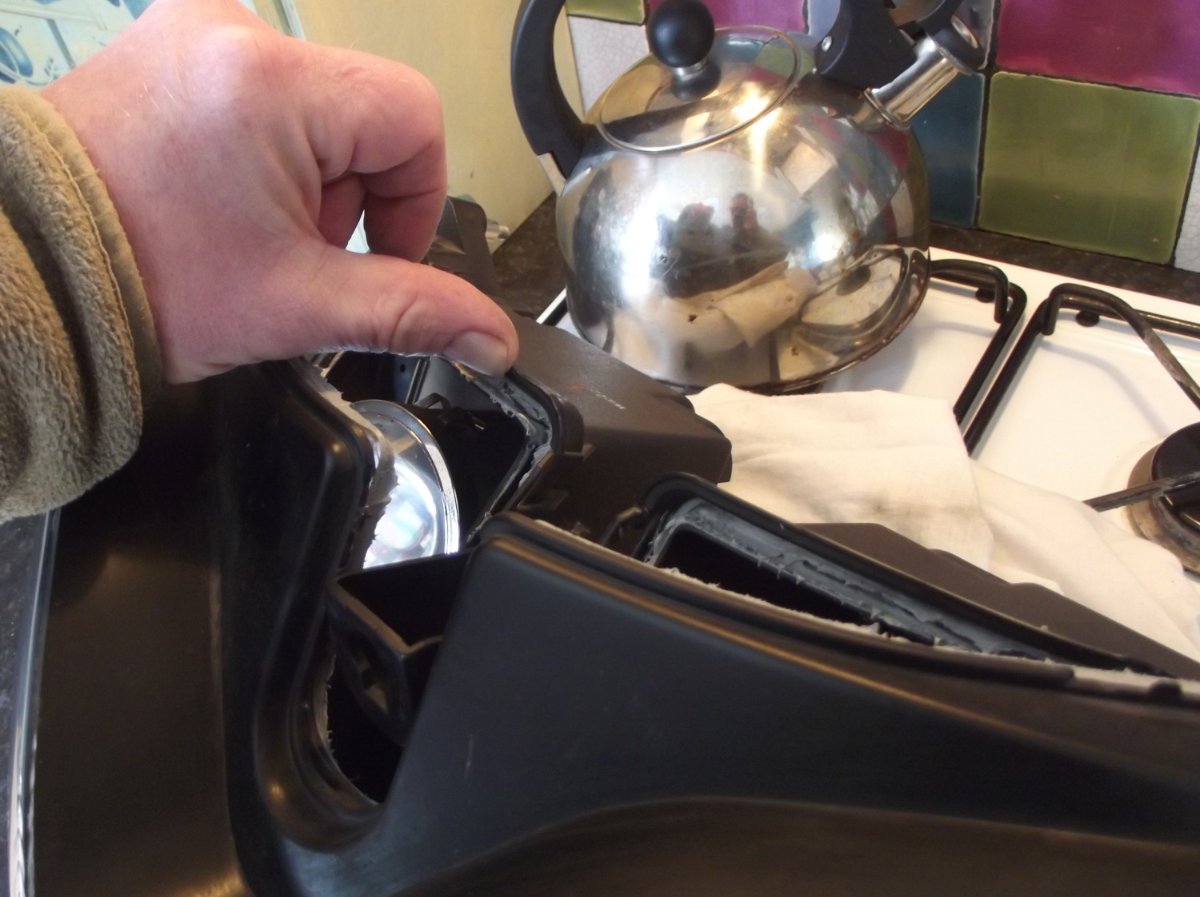
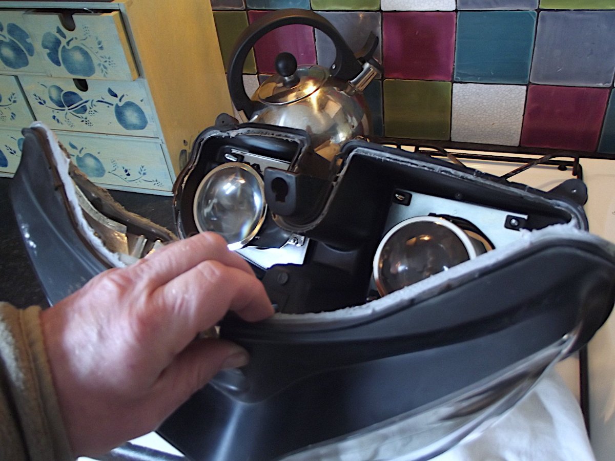
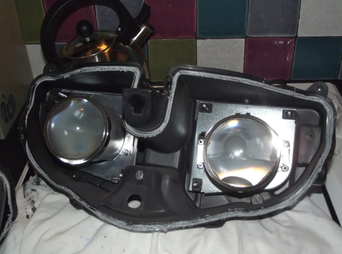
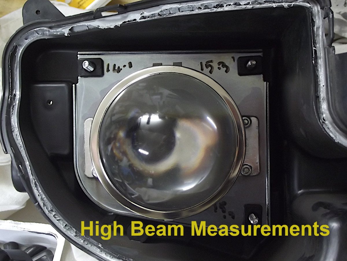
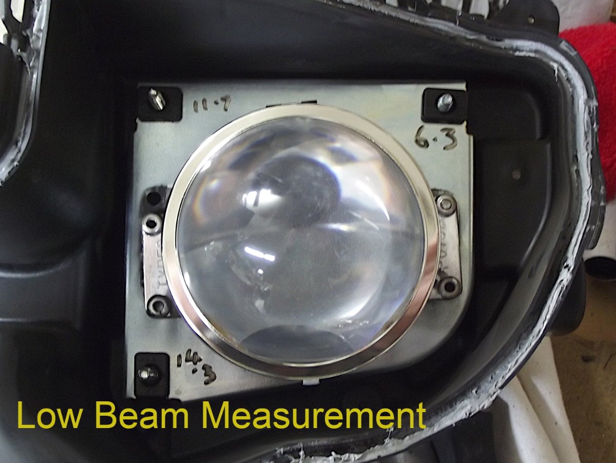
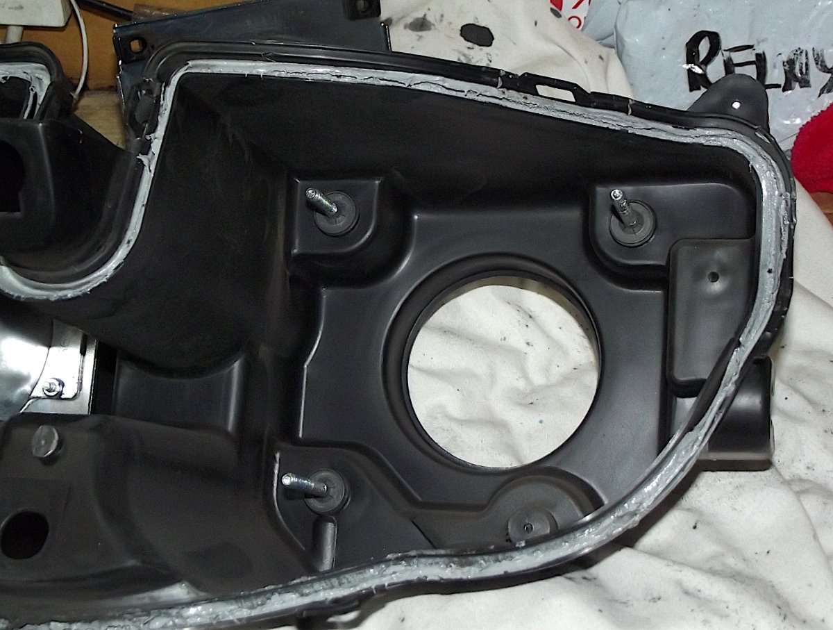
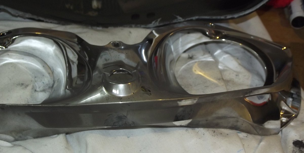
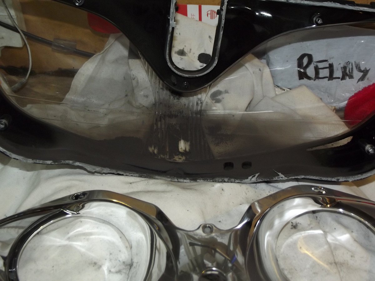
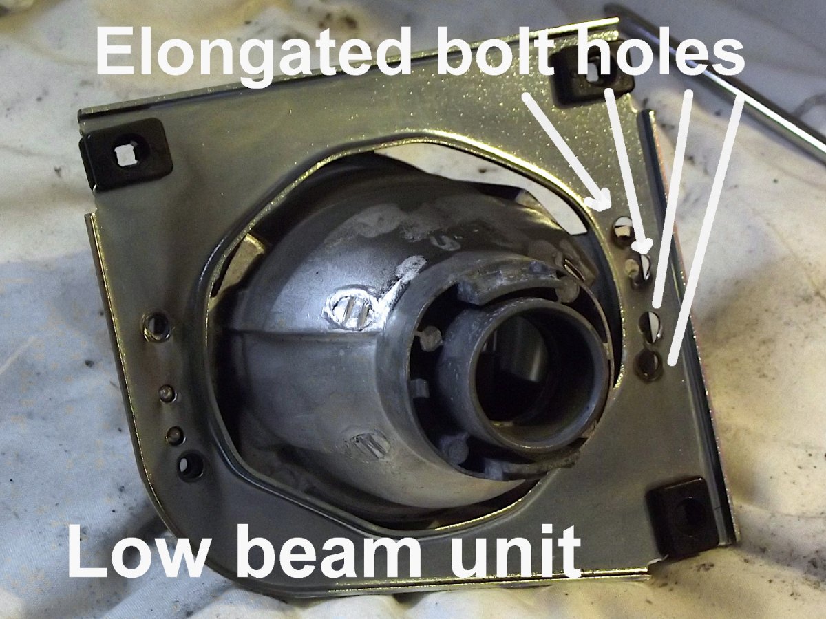
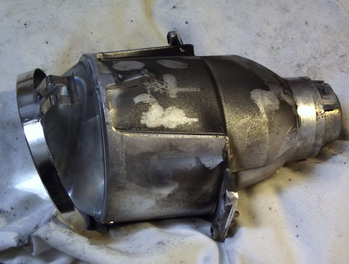
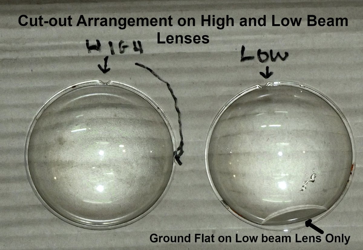
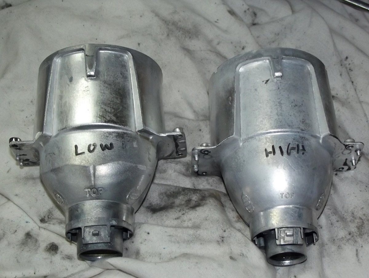
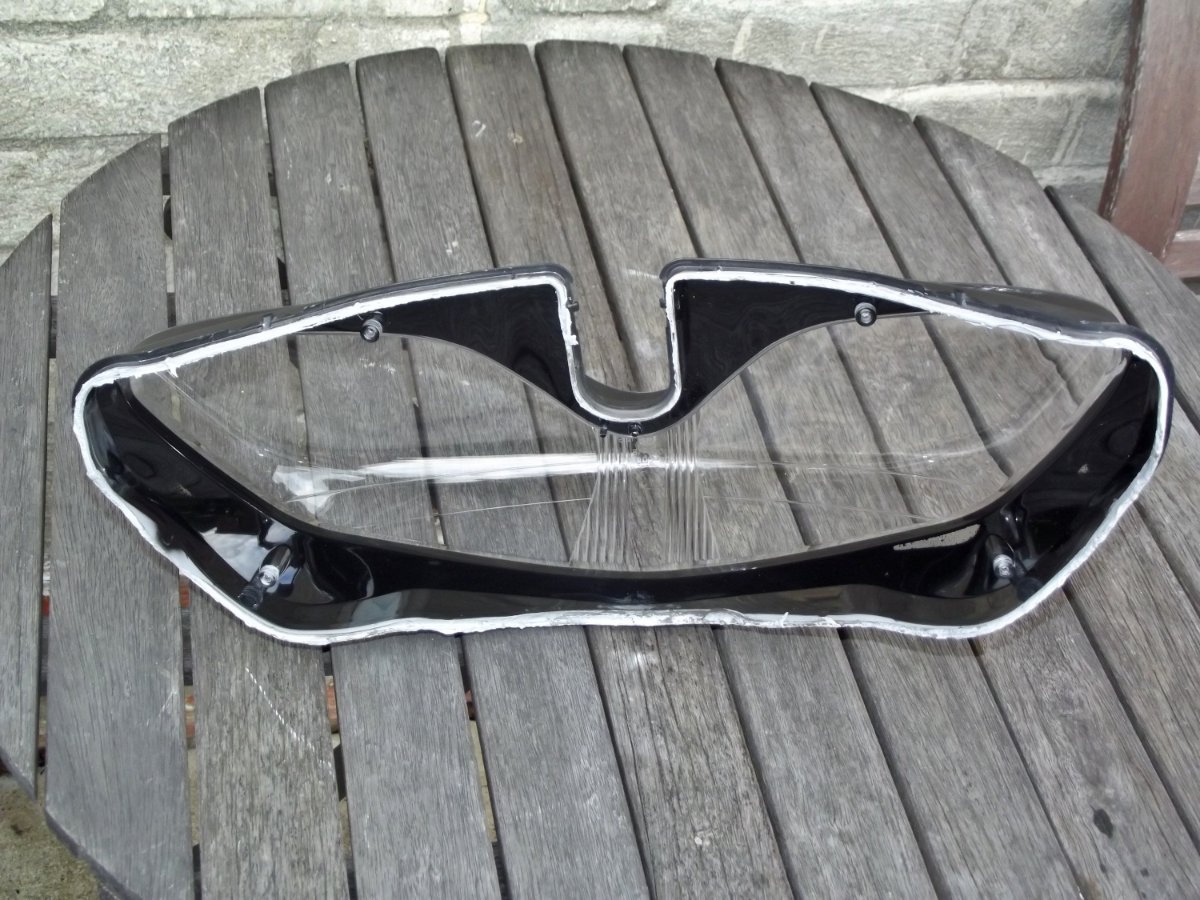
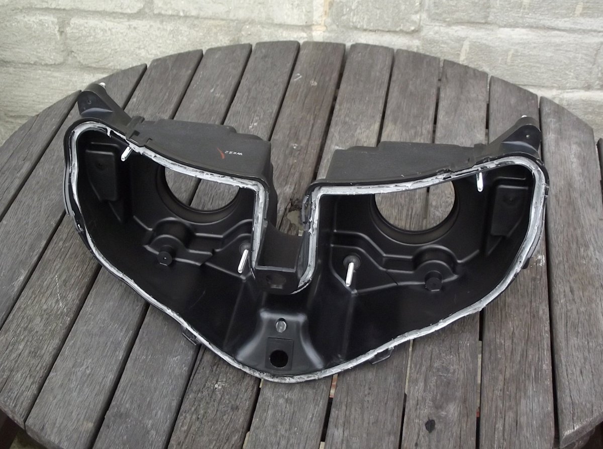
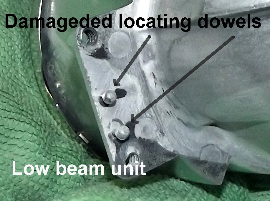
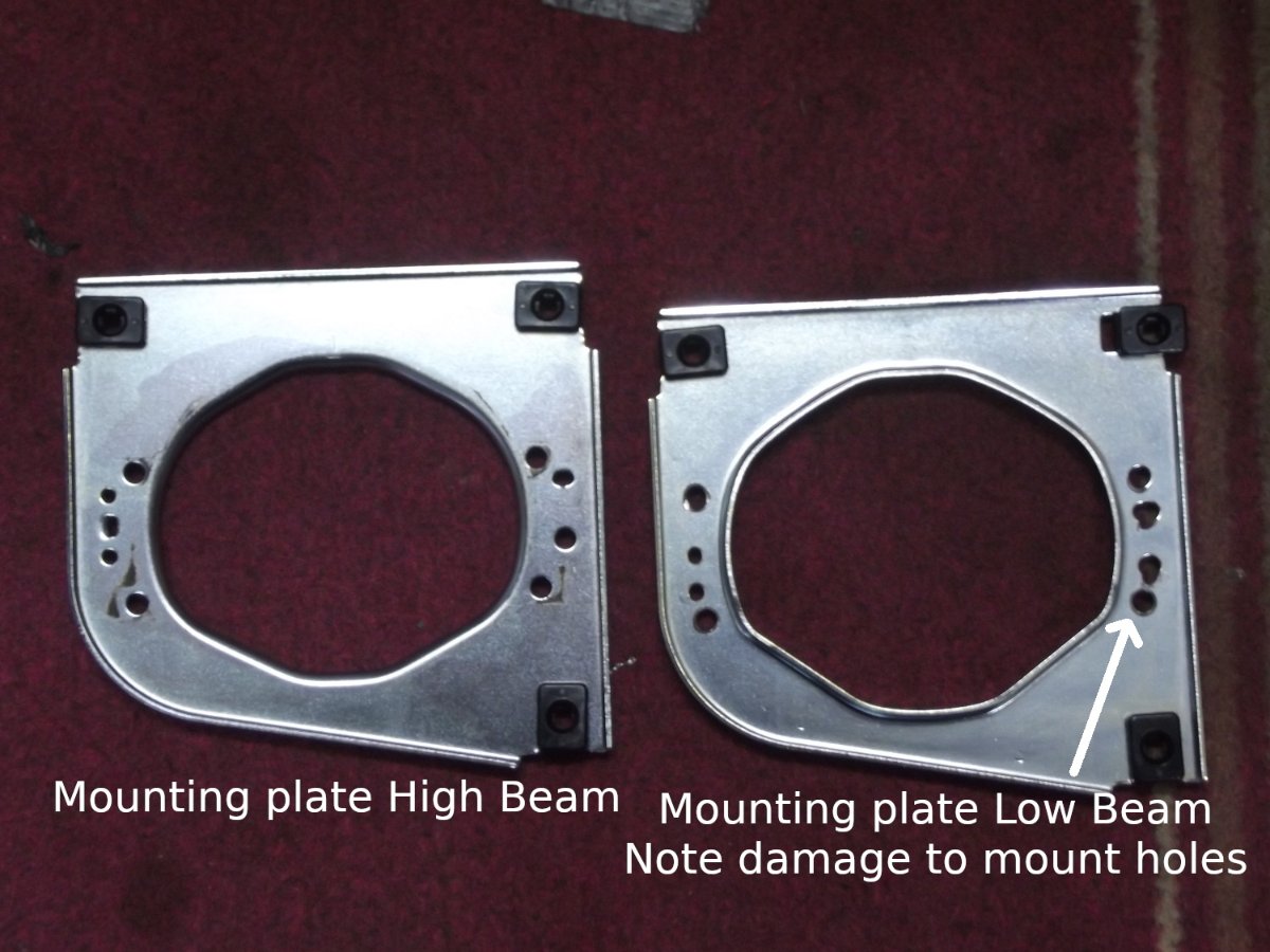
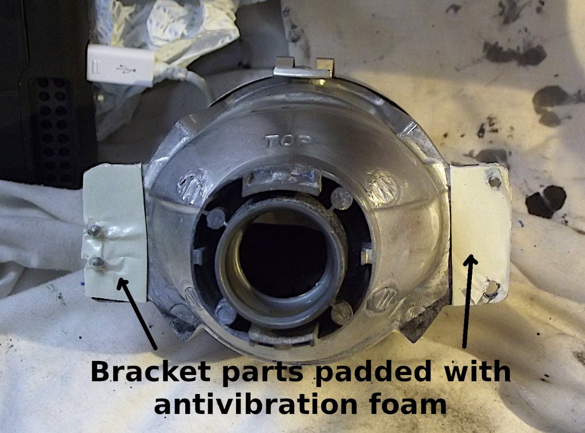
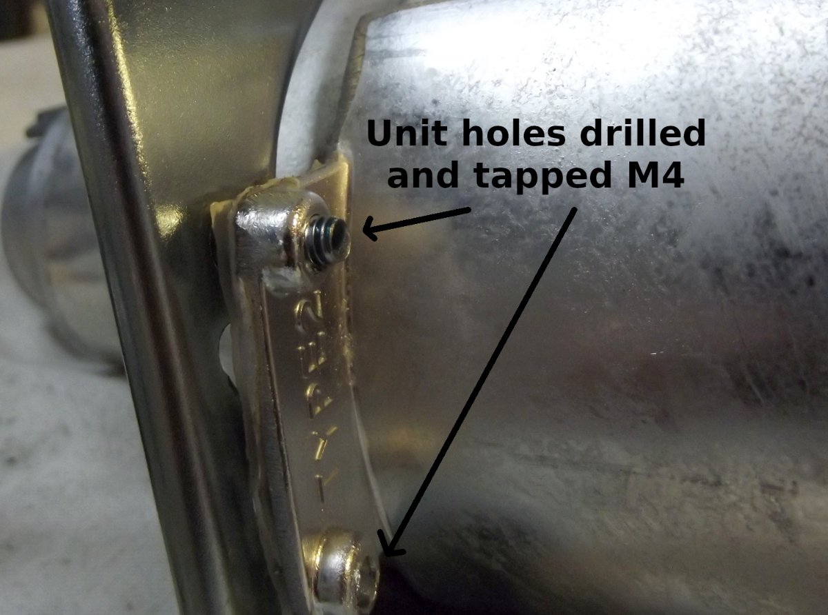
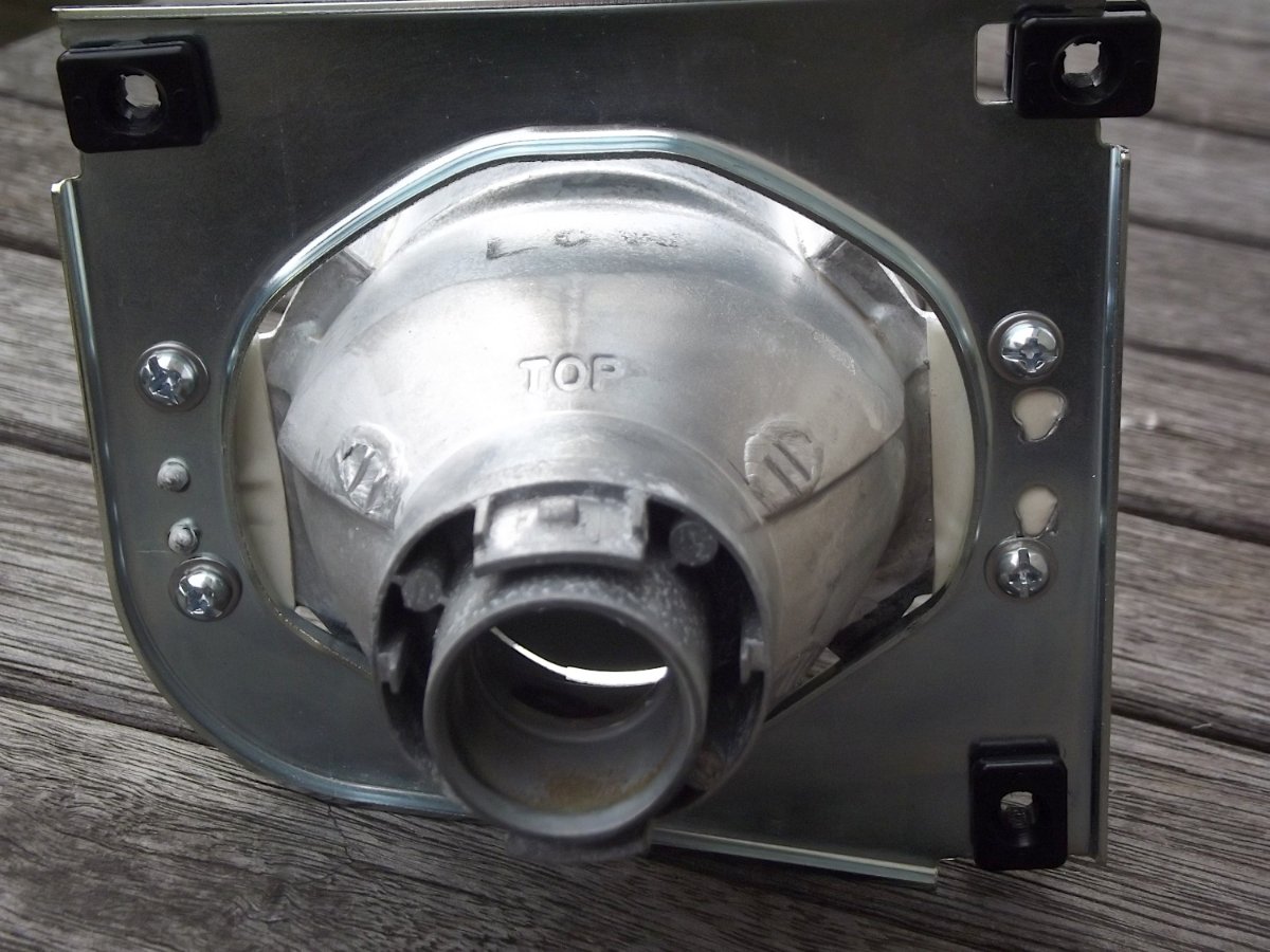
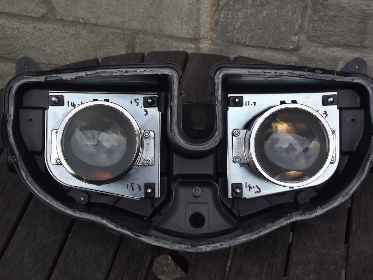
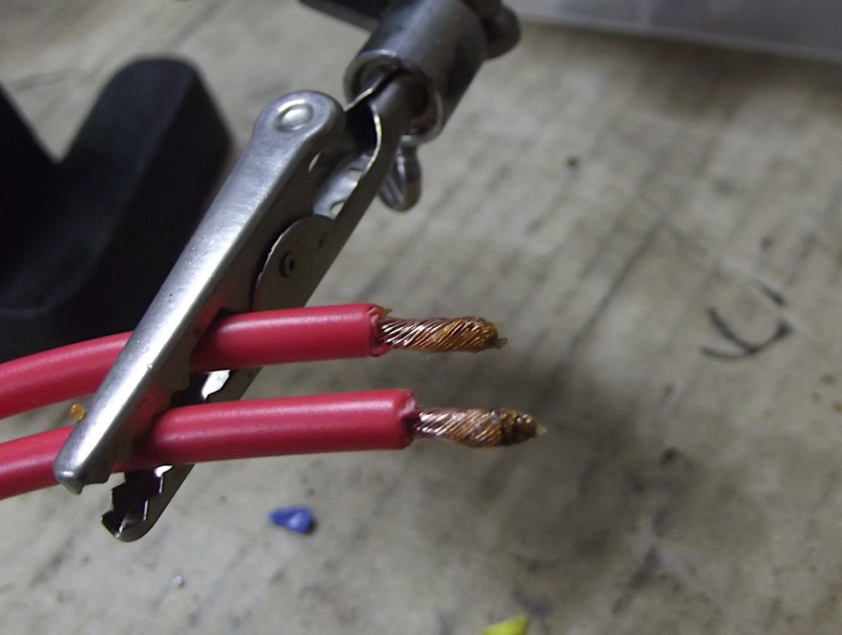
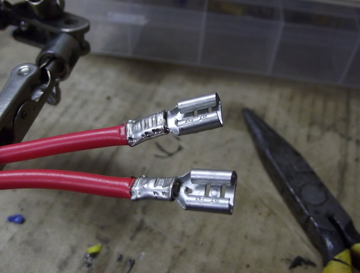
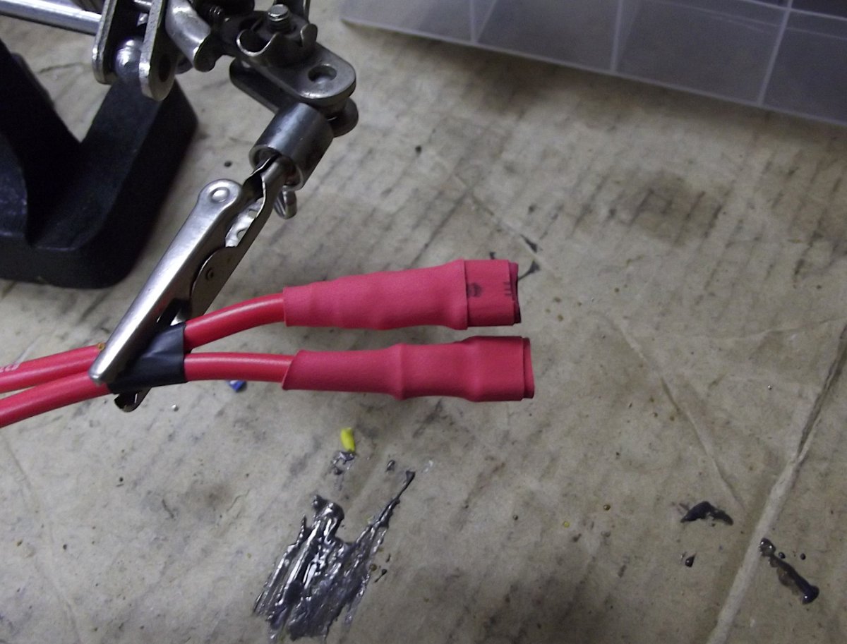
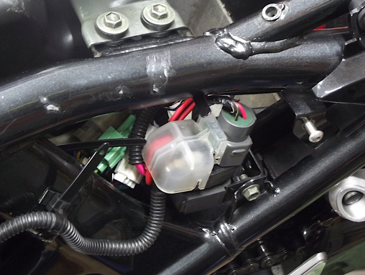
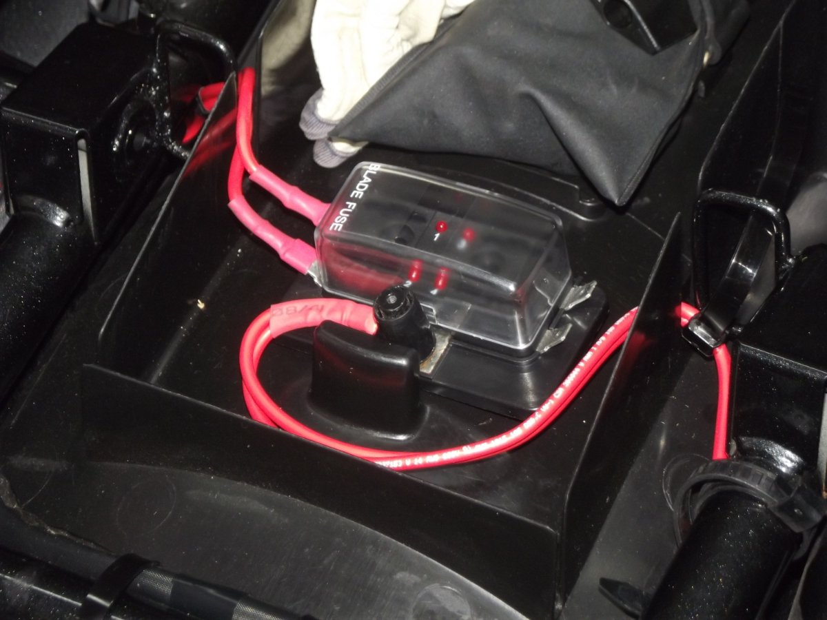
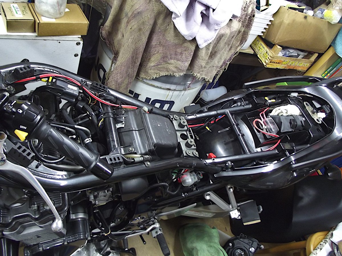
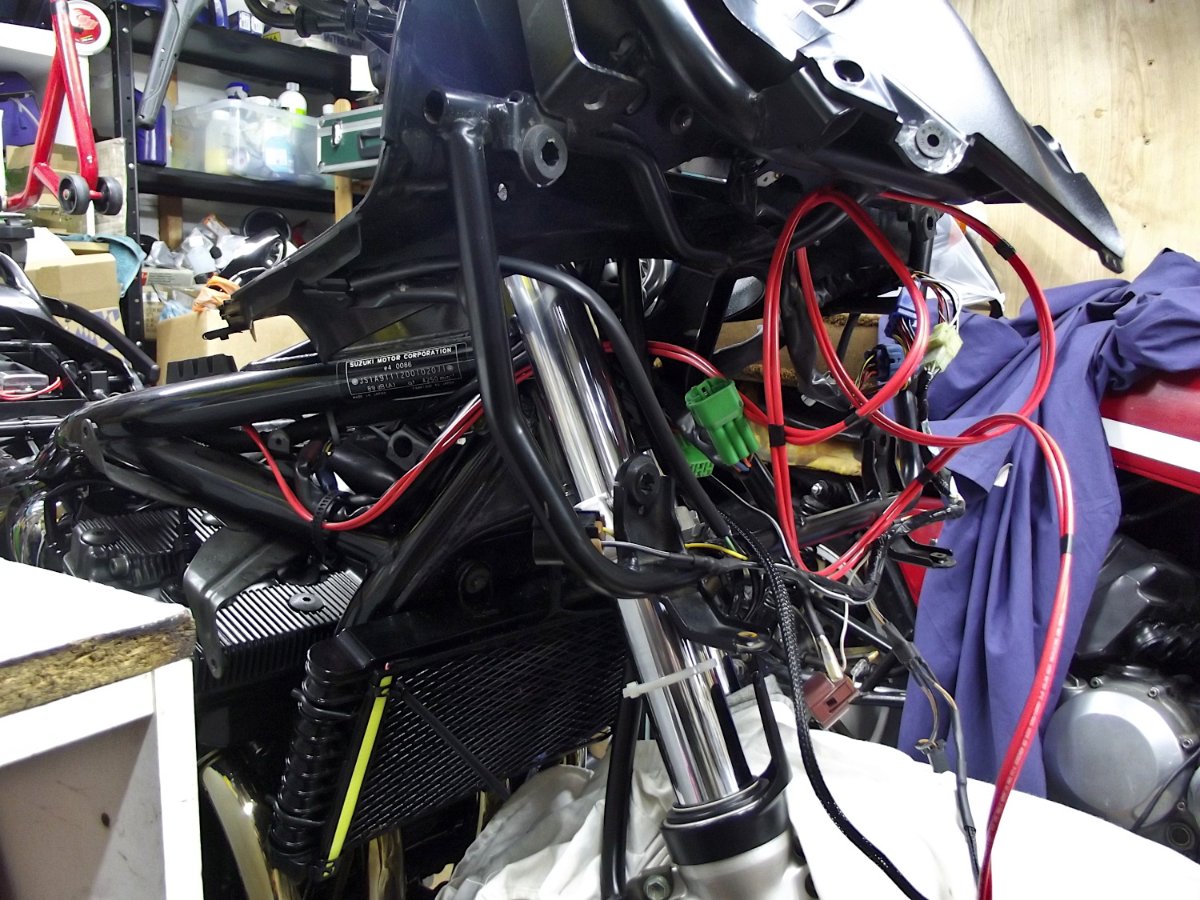
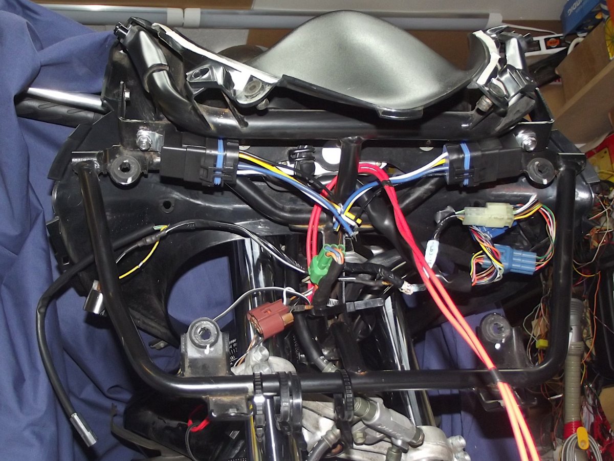
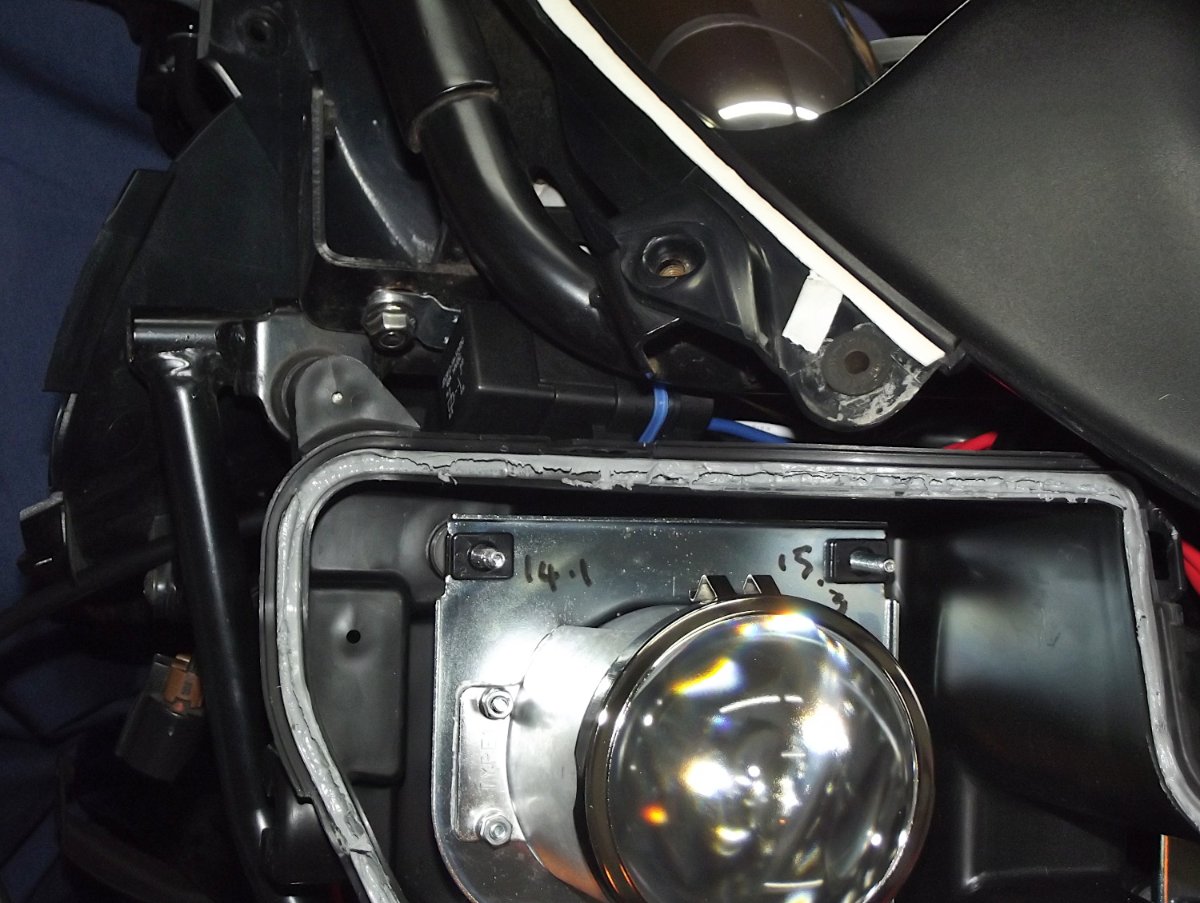
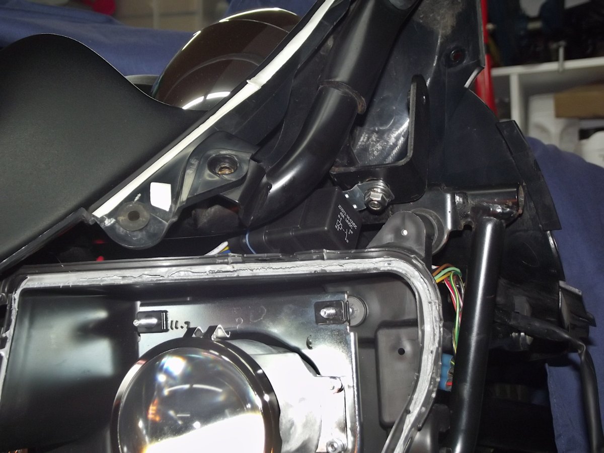
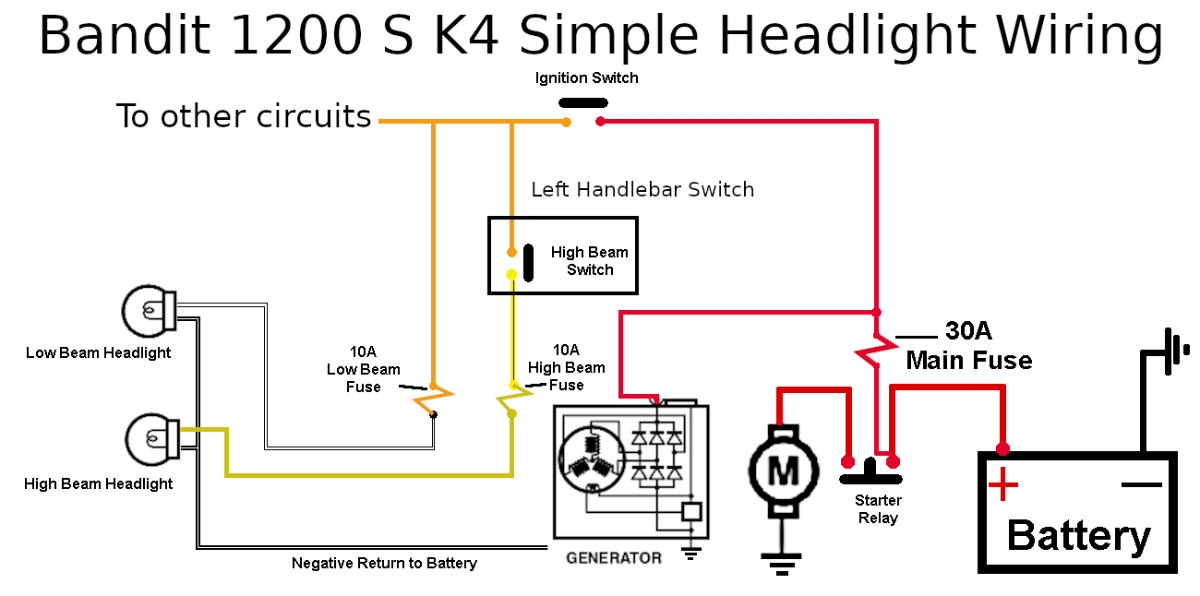
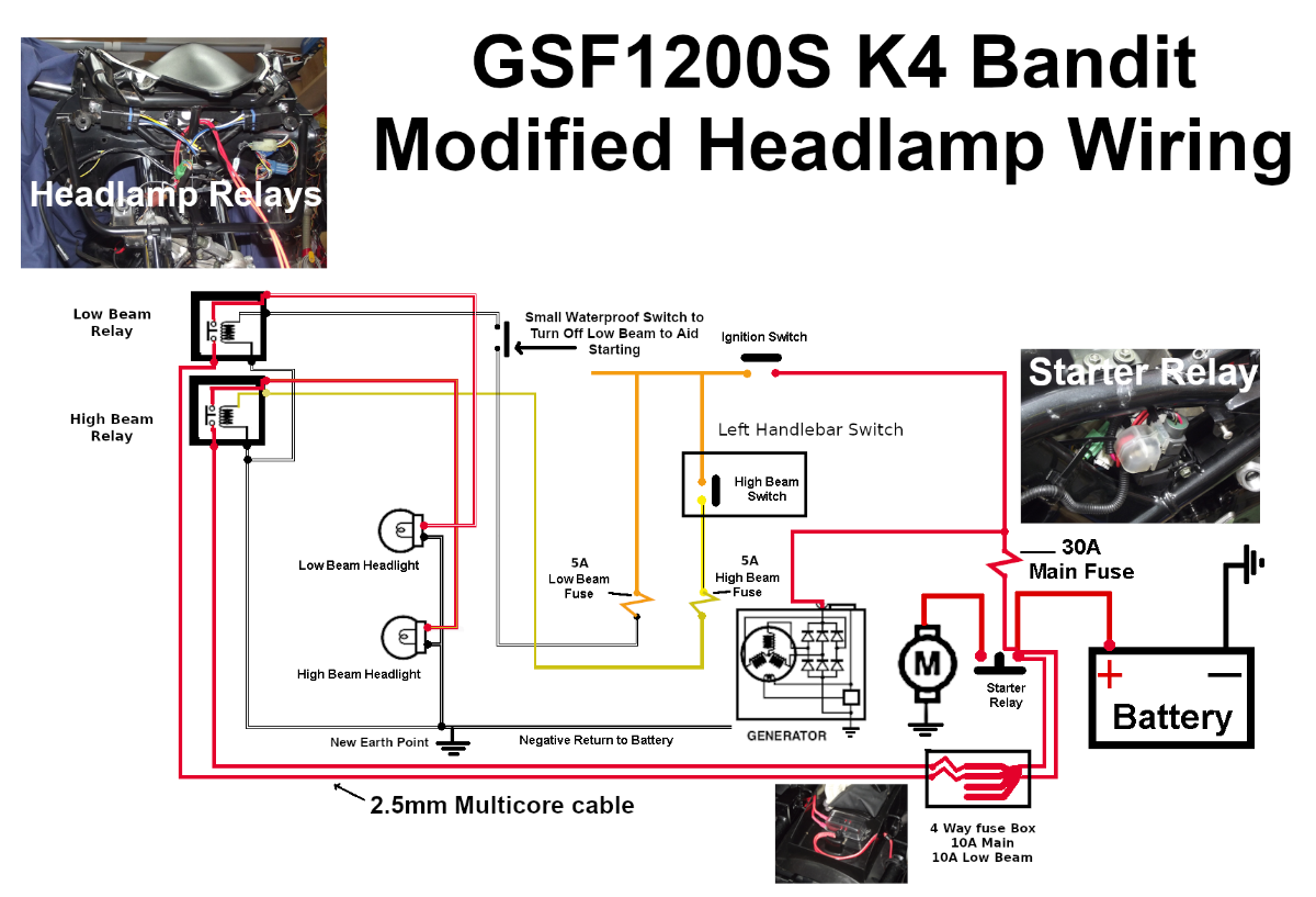
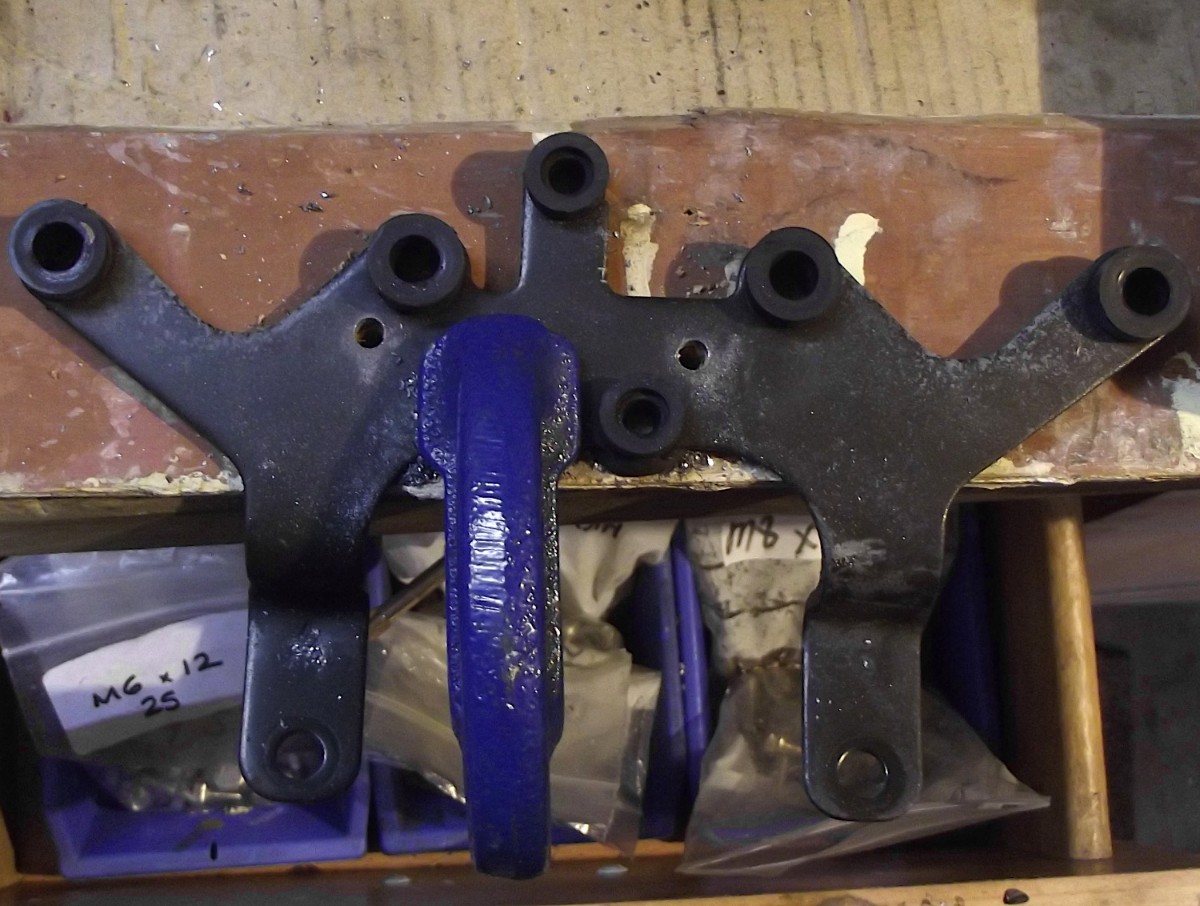
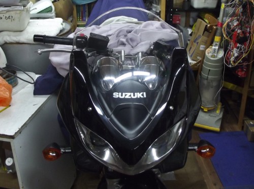
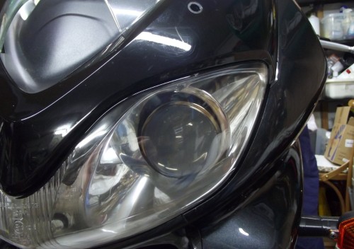
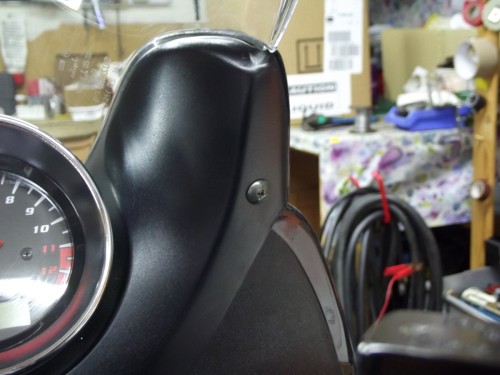
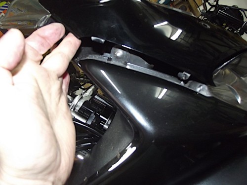
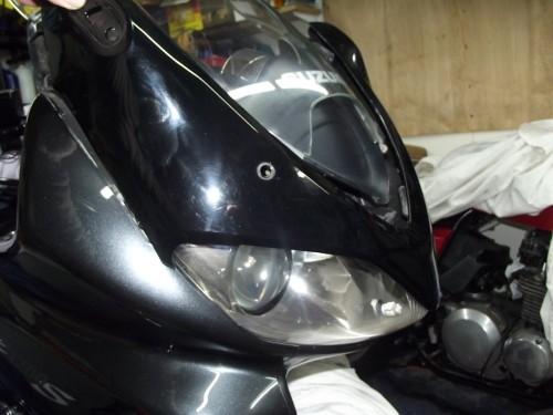
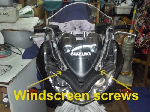
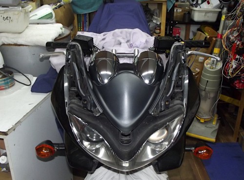
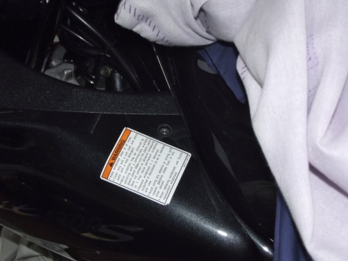
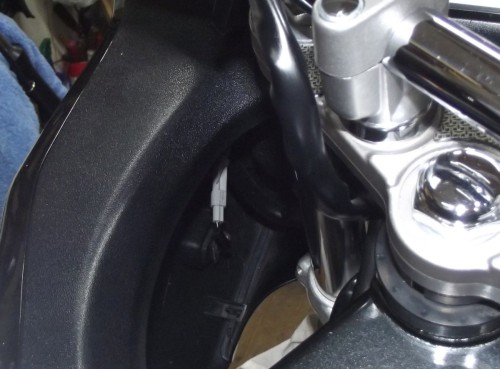
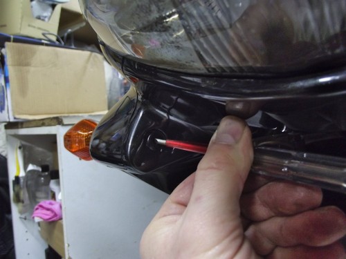
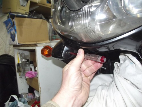
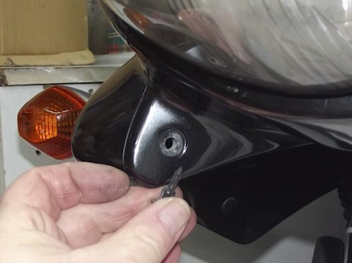
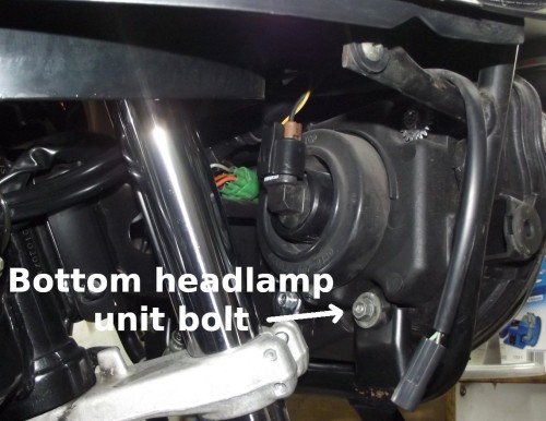
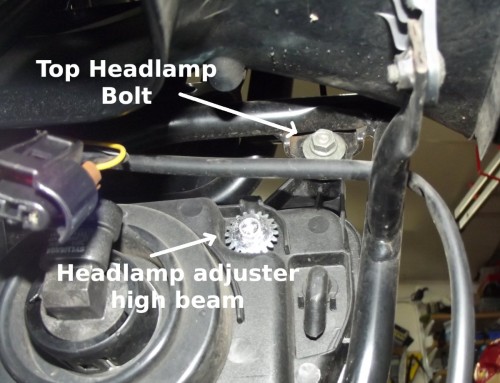
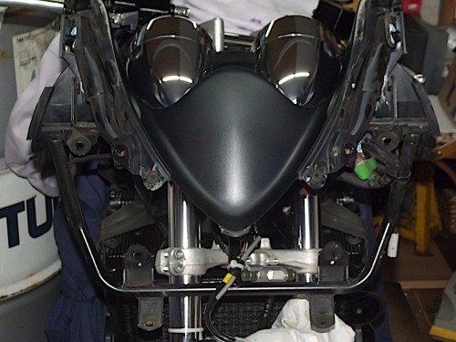
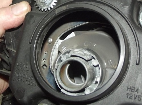
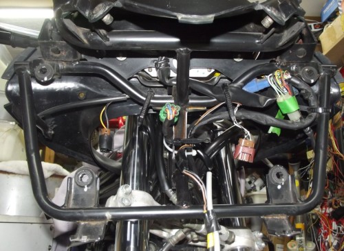
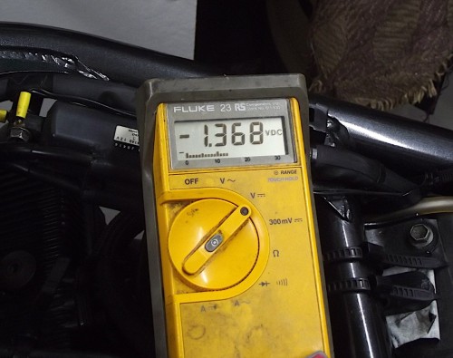
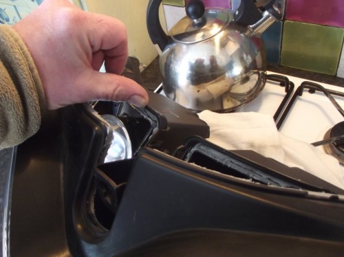
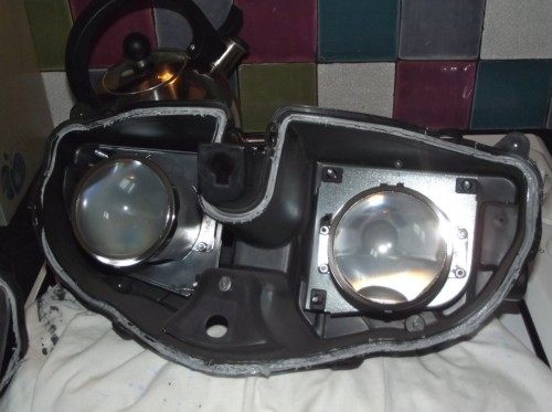
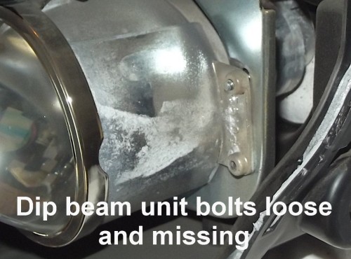
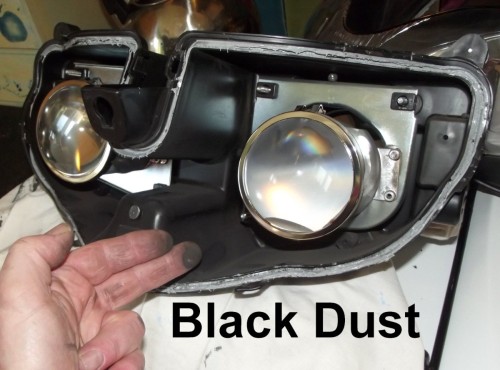
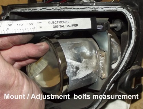
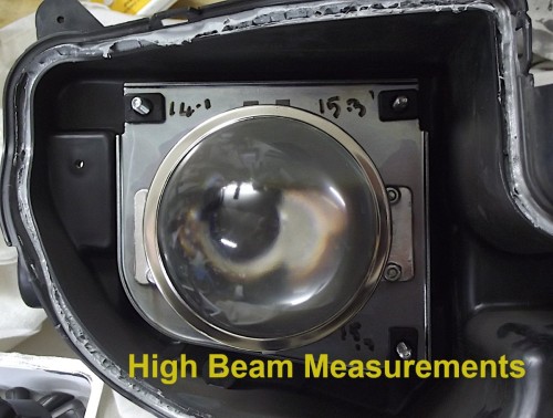
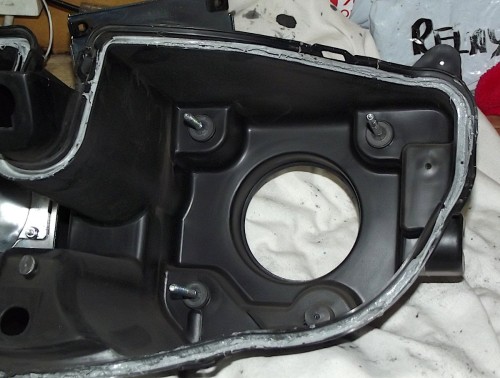
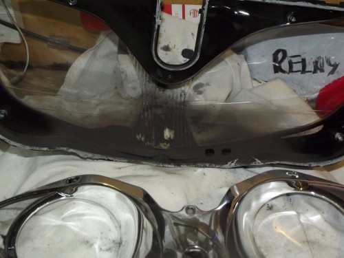
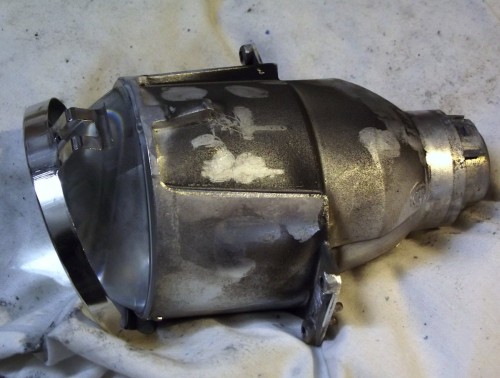
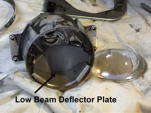
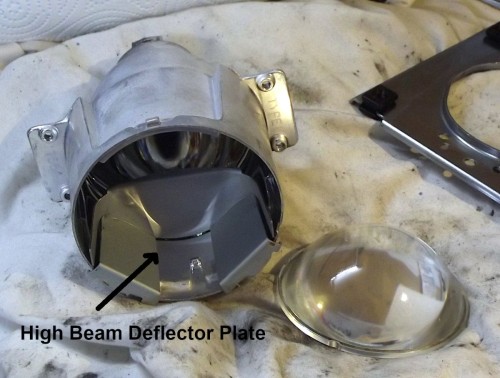
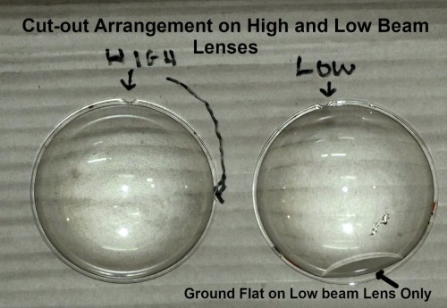
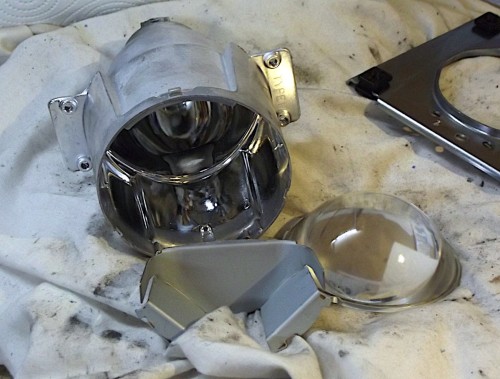
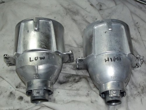
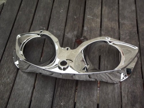
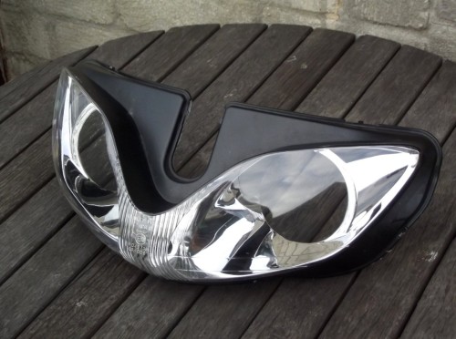
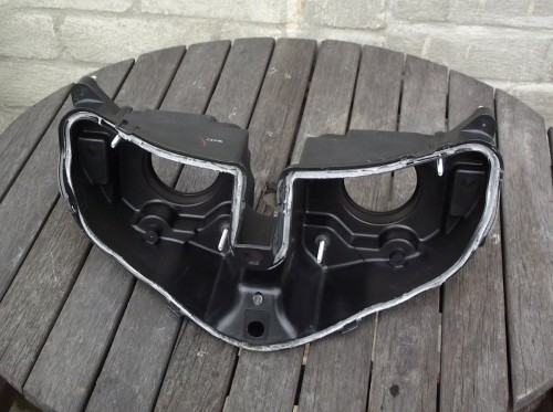
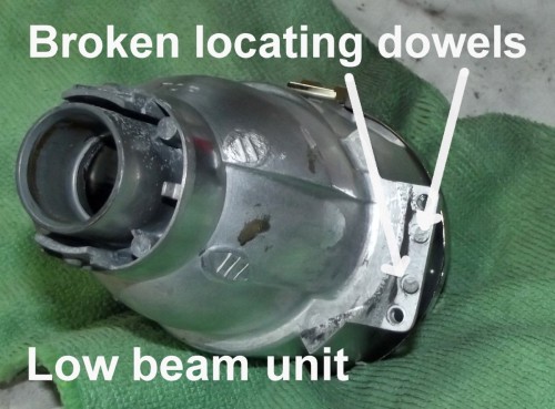
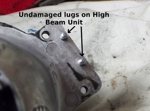
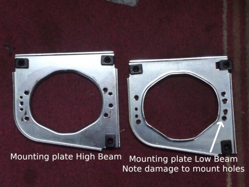
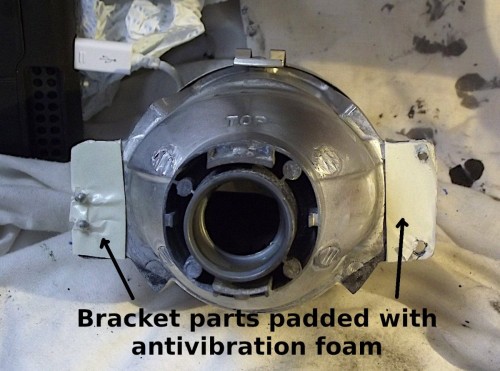
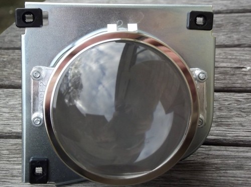
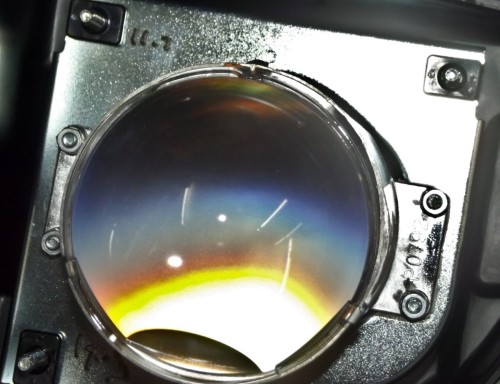
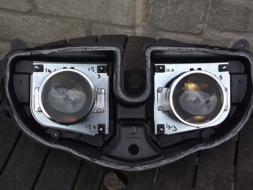
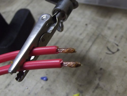
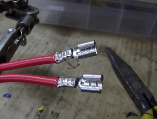
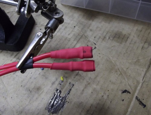
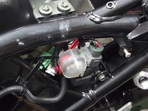
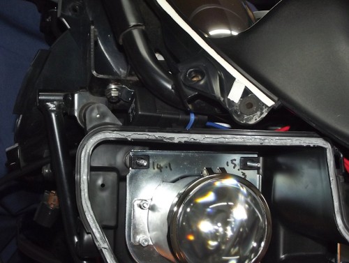
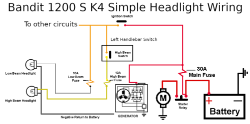
Suzuki GSF1200S K4 Bandit Headlight Repair. If you look anywhere on the internet regarding the headlights on the 2nd Gen Bandit S models 1200 and 600 you will find numerous instances of the problem I have with mine. Namely poor light output, dust inside the lens and buzzing. Admittedly 90% of the buzzing will be coming from the windscreen and other loose fitting in the front fairing. I noticed an big increase in buzzing around 3000 rpm lately so had a good look round the area and discovered the low beam projector unit had dropped in the housing. While it’s out there are a few other jobs to do in this area. As with most Japanese bikes the main cause of dim headlights is the thin wire used to wire the bike. These lamps as STD are around 55w so at 13.5v will pull around 4 amps. The power for these lamps has to come from the battery of course, via the main 30a fuse on the starter relay, ignition switch, dimmer switch on the left handlebar, back to the fuse box in the tail section and finally to the headlight bulb. A route of around 2.5 metres. I measured the difference between the battery voltage and the voltage across the either headlight bulb. It was almost 1.4V. This is around a 10% volt drop due to the resistance of the small bore cables having to flow a current of 4 amps over a 2.5 metre run. I used a volt drop calculator to find the size of cable required to give a maximum 2% volt drop from a load drawing 4 amps at 13.5V over a distance of 2.5 metres. A cable size of 1.5mm cross section would be just adequate so I chose 2.5mm cable. A point to remember is that a volt drop occurs on the positive run and also on the negative route to the battery. On the Bandit the negative wire (black with white tracer) is of a slightly larger size than those of the headlamp wires, but this has to be used for all the other circuits as well. I will run a separate 2.5mm negative wire from the headlamp wiring loom to a suitable bolt on the main spine of the bikes frame. The following parts were ordered: 10 metres of 2.5mm Red and 2 metres of 2.5mm Black cable 2 x 12V 40A fully waterproof automotive relays with connectors. A 4 Gang fuse holder Headlamp removal. Fairing removal. Mirror removal is very straight forward with them being held on with 2 Allen bolts each. To remove the front cowling the 2 bolts on the top are removed first. Then the 2 cross headed self tappers on the rear inner clock shroud. The cowl is lifted at the top to pull out the tabs on the side then it is removed by pulling forward from the front. The windscreen is held with 2 screw at the bottom. It is removed by lifting the screen over the 2 tabs on the upper fairing where the mirrors are mounted too. Before you remove the bottom cowl it is a good idea to first remove the bolts holding the fairing side panels. This allows a bit of wiggle room necessary to get the cowl out. Start with the top back bolts to the side of the tank, then the 2 side screws. and finally the one above the headlamp unit which was hidden by the top cowl. Then disconnect the indicators. When the 2 Allen screws have been removed from under the bottom cowl the 4 plastic rivets can be removed. To do this press in the middle part of the rivet and pop out the entire rivet. With all the panels removed both the main and dip bulbs were disconnected. The entire headlamp unit is held on to the fairing bracket with 4 M6 nuts and 4 large M6 washers. With these removed the unit is pulled forwards and released. The pilot light bulb and holder can now be removed from the headlamp unit. With the unit fully removed and on the bench it was easy to see one of the projector unit mounting screws laying loose in the bottom of the cover. After removing the low beam bulb, rubber collar and plastic adaptor you can see 3 of the 4 projector mounting self tapping screws have fallen out and the remaining screw is loose. The projector unit for the main beams screws were still tight but they all are going to be replaced with bolts and nuts. Headlamp unit Disassembly The easiest way to remove the front lens is to heat the unit up in an oven at around 80C for 15 mins to loosen the glue. All the vent pipes and plastic fittings together with the mounting rubbers were first removed before heating. Before removing the projector units I measured the thread length of the mounting bolts to maintain the rough alignment when reassembly. The 4 self tapping screws in the main beam unit and the remaining bolt in the low beam unit were removed and the all components washed in warm soapy water. Below you can see the damage. you can see now where that black dust came from. Each projector unit’s lens is held in place with a circular ring clipped to the body. Although they look similar the units are subtly different. Low beam unit fully disassembled, note the beam deflector on the underside as the projector lens inverts the beam. The beam deflectors are a similar shape so I made a mark on each to aid the correct reassembly. Here are the parts after cleaning. Projector Units Reassembly The low beam unit required the most attention as 3 of the 4 self-tappers had dropped out. This caused the locating dowels to shear off and elongated the mounting holes. The mounting plates. In addition to nuts, bolts and Loctite a small thin layer of foam was glued to the mating surfaces. Projector Units Refitting The mounting holes on both the low and high beam units were drilled and tapped M4 before M4 X 16mm screws were loctited into place. To make doubly sure M4 nuts were also fitted. Low beam unit reassembled and fitted to the mounting plate. The final job after the main beam unit was modded was refit them to the housing and reset the plates into their original position using the measurements taken on disassembly. Headlamp Relay Conversion. The standard headlamp wiring on a 1200S K4 Bandit has the dip beam on all the time with the ignition in the on position. The circuit was modified to use 2 waterproof relays, one for low beam and one for high beam. These relays are operated by the standard low and high beam wires. New larger wires run from the battery side of the starter relay, via a new fusebox, through the main contacts of the relays to power each headlamp. A new larger negative wire was also used to provide a better return path to the battery via the frame. A small on-off switch was added to the low beam relay circuit, reducing the load on the battery at startup. Main 2.5mm cables crimped, soldered and insulated to run from new fusebox to relays Wires ran from Battery side of starter relay to new fuse box and then out and routed to the front of the bike. Relays test fitted Headlamp temporally unit fitted, there is just enough space. Thant's as far as i have got, wiring up next. Watch this space


-
Got a few miles done before the weather closed in. All running well. Over winter will price up a replacement seat cover. P & K look a good bet. Also some new tyres for the spare gold painted wheels. Mitchies or Avon??? Anyhoo all tucked up for winter.
-
Moving to London very anxious about my bikes
linuxrob replied to Leanbiker's topic in Motorbike Chat
Welcome to the forum. Motobob on YouTube has done a few vids on keeping you bike safe. They a good starting point. Regards Rob B -
Fixing up (old) chinese bike
linuxrob replied to Jim's topic in Old Motorbikes, Projects and Restorations
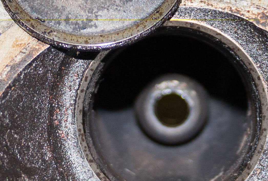
That motor looks Suzuki based with that oil filter cover. -
Triumph Trophy Engine Strip
linuxrob replied to Mickly's topic in Old Motorbikes, Projects and Restorations
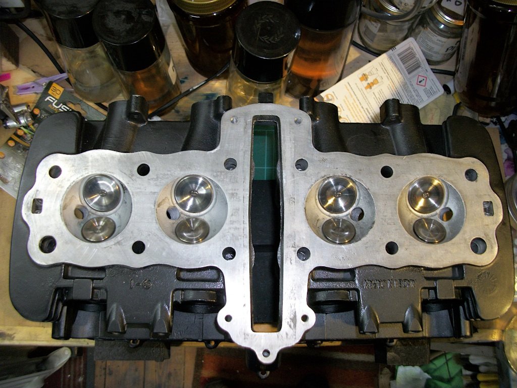
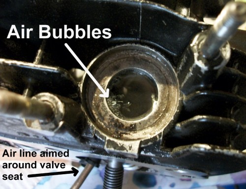
Even though my Z500 valves passed the liquid leak test they looked like yours. I filled the port up with water and blasted my airline around the valve seat in the combustion chamber and saw bubbles at certain points. a light grind in sorted it. worth a try just keep them press in with the spring compressor no need to refit the collets to test, see photos Regards Rob

-
Replica KOSO speedo install GS125
linuxrob replied to linuxrob's topic in Old Motorbikes, Projects and Restorations
IP Rating .... ? IP 44, splashproof!!!! Oddly enough was thinking of that, will look on eBay for a nose fairing off a GS125 or maybe a small flyscreen. With it's eBay, Exhaust, carb, day running lights, heated grips, camshaft and now Speedo I could paraphrase "The Vapours" and it's turning Chinese!!! Rob B -
Yesterday to be honest but it did take all day!! Fitted a KOSO copy speedo / tacho unit to the GS125. Full story here is you have trouble sleeping tonight. https://www.themotorbikeforum.co.uk/viewtopic.php?f=87&t=73922&p=1158483#p1158483 may be of use to anyone getting one of these. Rob B

-
Brilliant Stu, just brilliant
-
Replica KOSO speedo install GS125
linuxrob replied to linuxrob's topic in Old Motorbikes, Projects and Restorations
Well Bob, you know.... I need to get out more -
Replica KOSO speedo install GS125
linuxrob replied to linuxrob's topic in Old Motorbikes, Projects and Restorations
Cheer Tim They are quite light and epoxied to the inner part of the disc so will not affect it.It is a GS125 and 60MPH is a fantasy on this bike. -
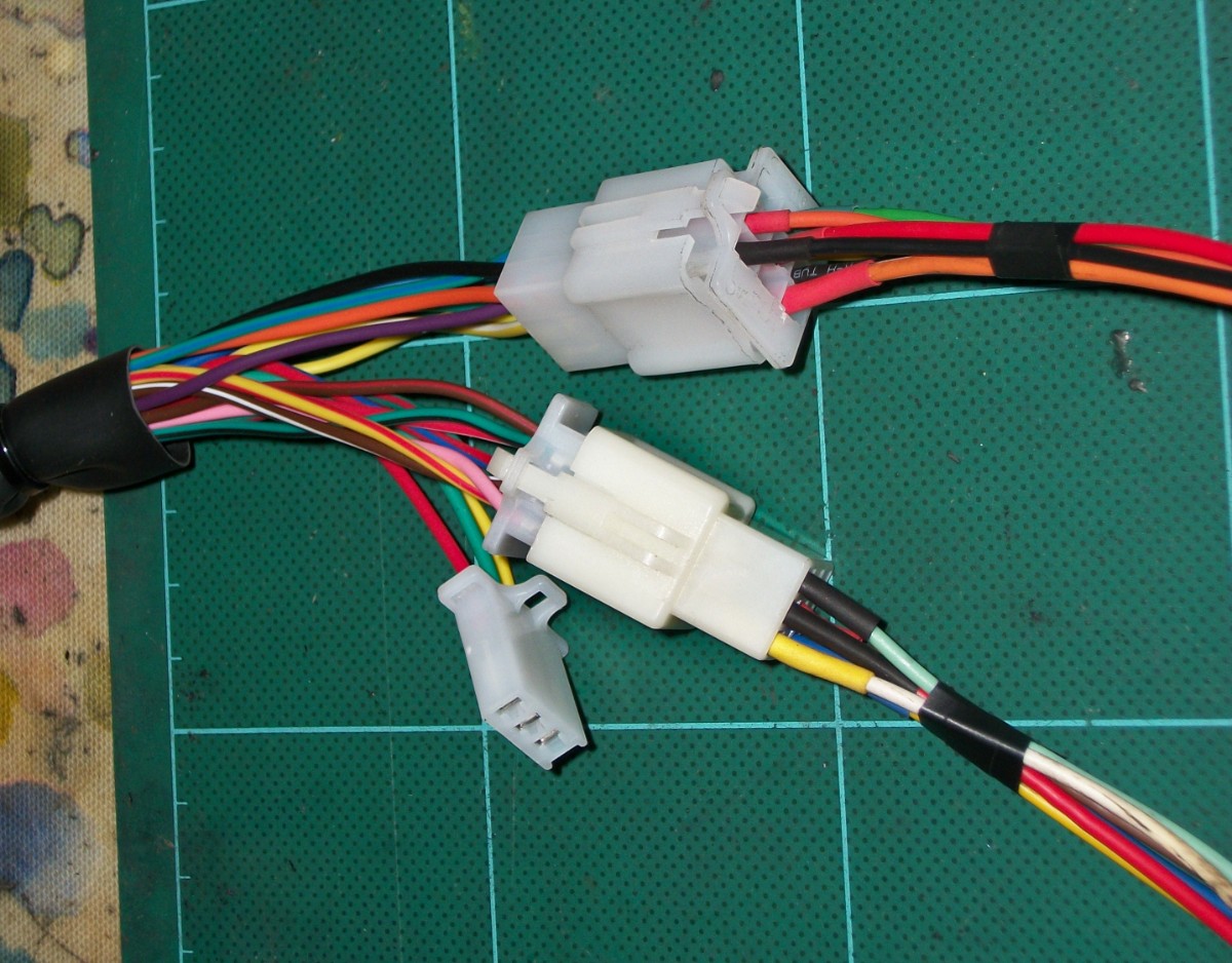
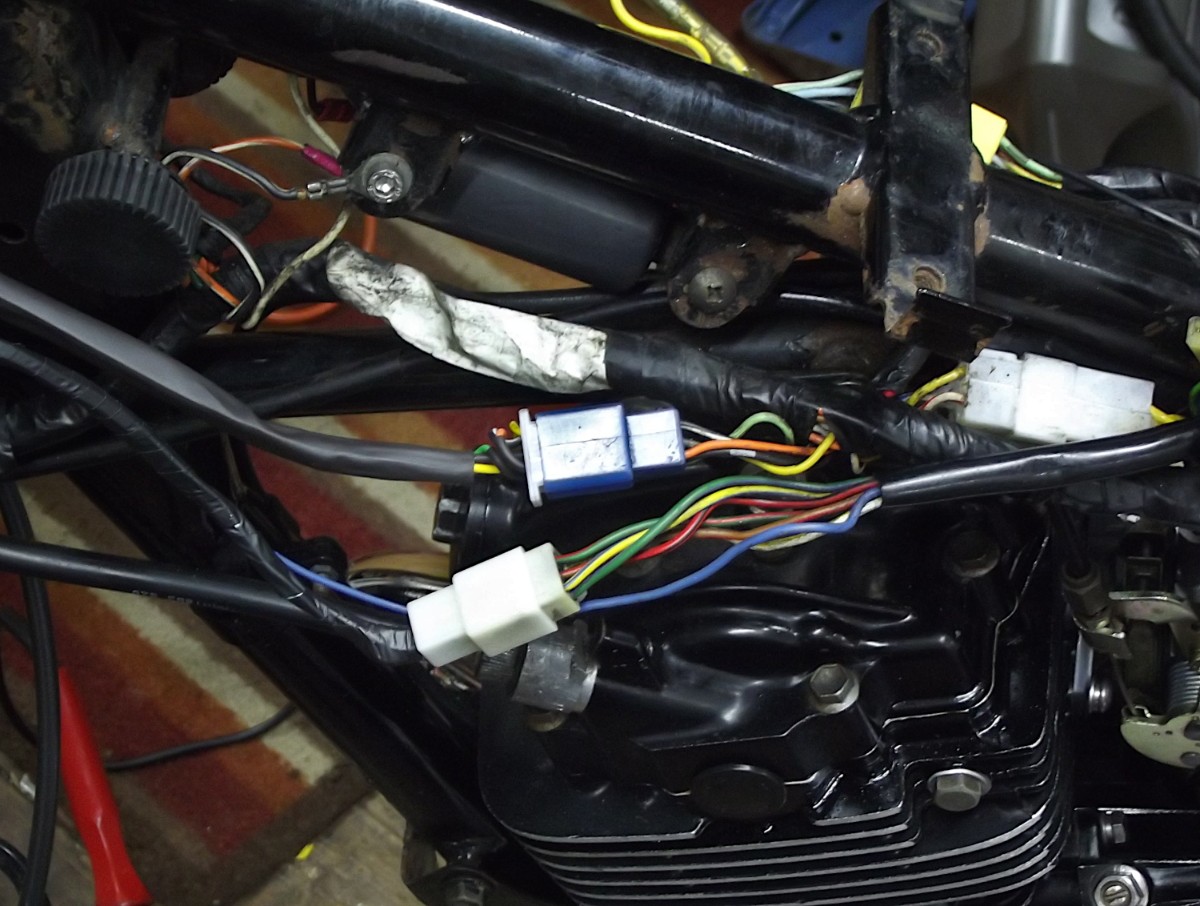
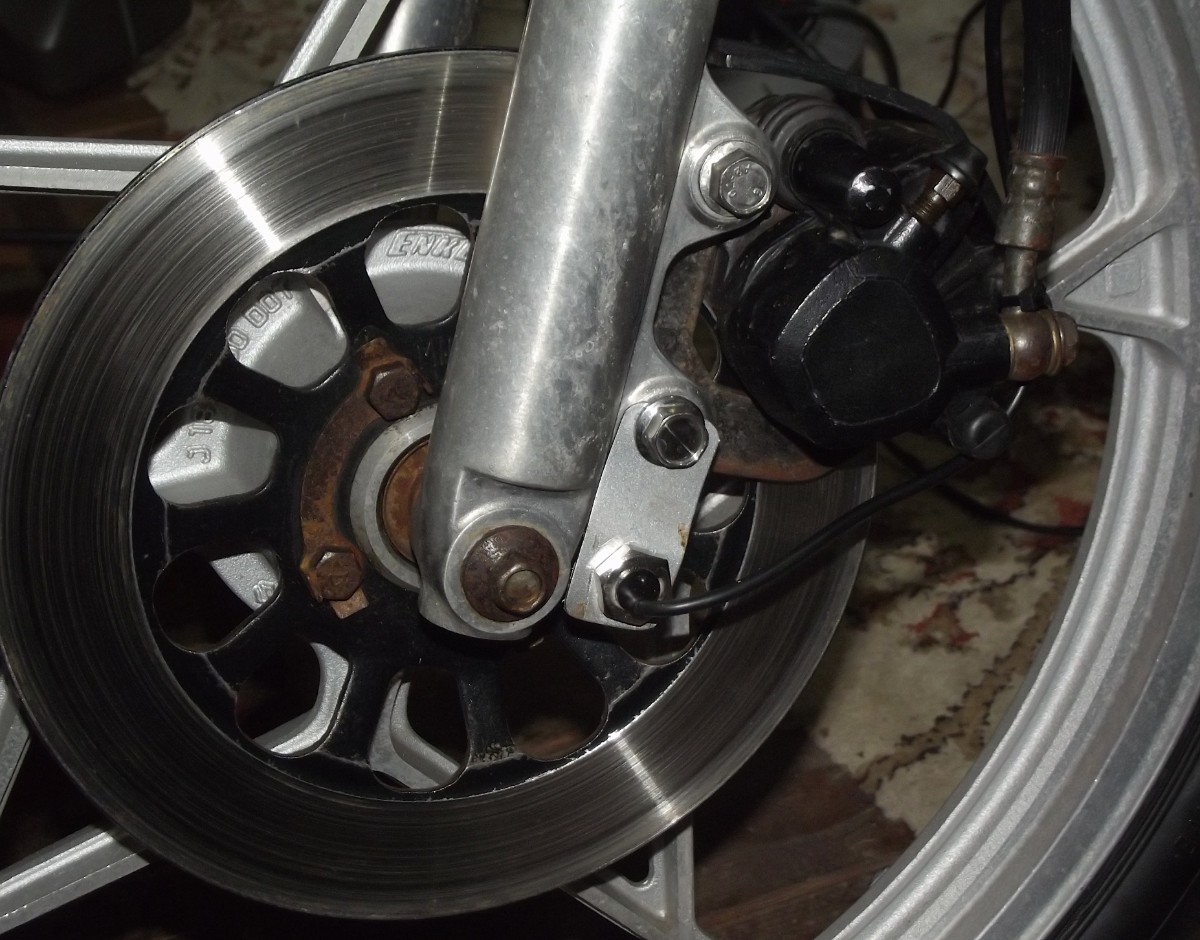
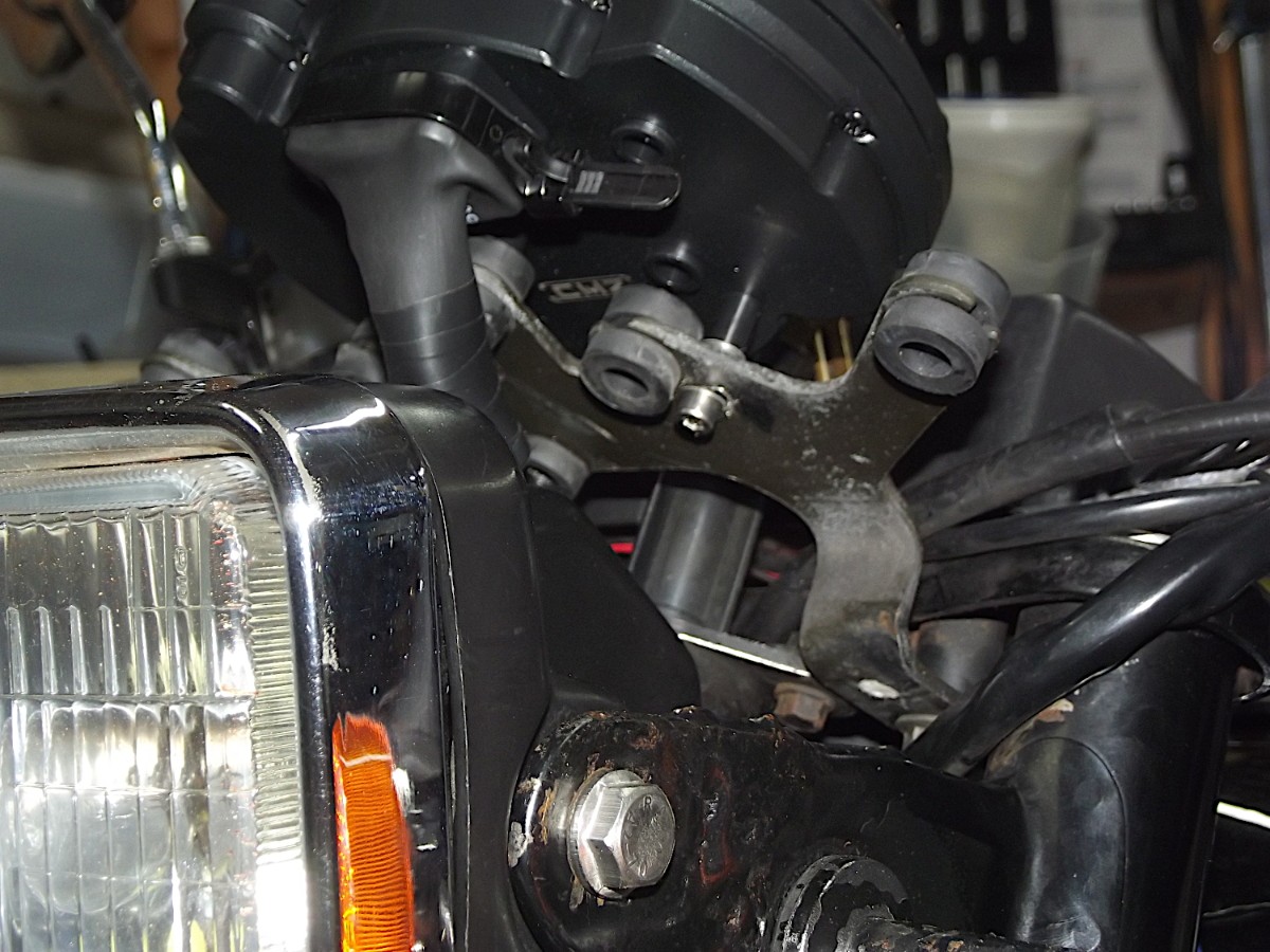
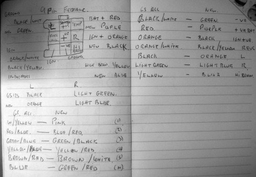
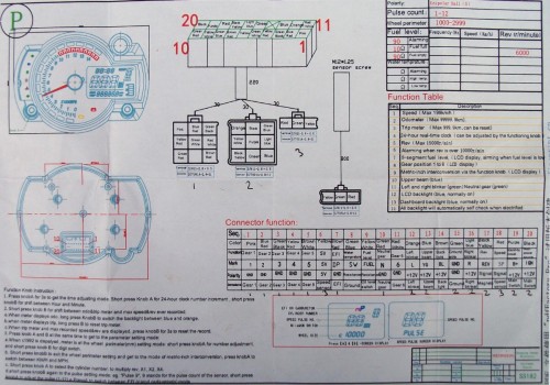
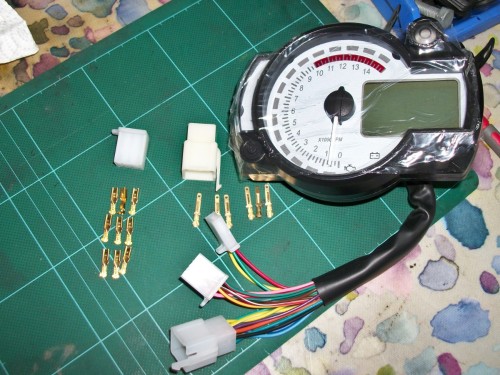
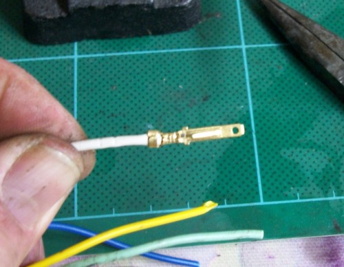
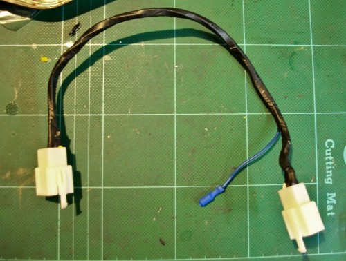
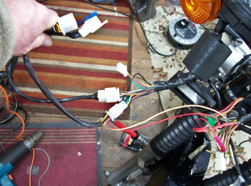
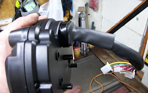
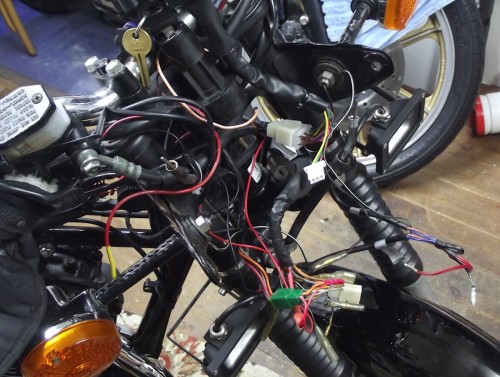
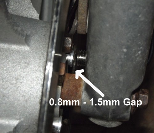
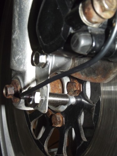
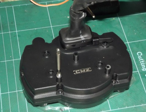
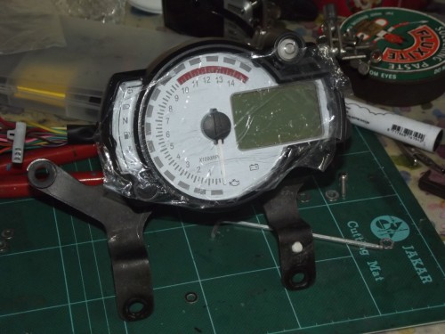
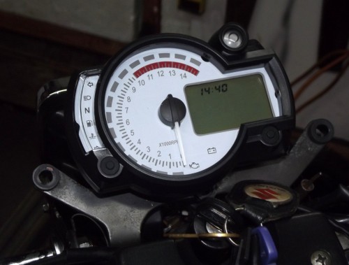
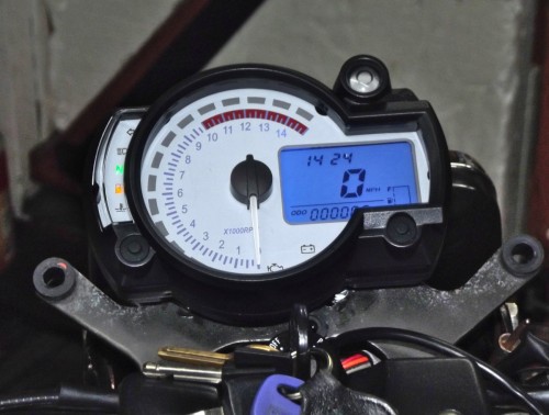
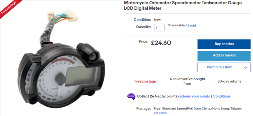
GS125 Speedo replacement There now follows the usual rambling, oversimplified, and photo overloaded waffle documenting the latest job done on a wet afternoon in the shed as it's wet and there's nothing on the telly. The GS125 tacho has never worked thanks to a shattered drive worm gear (previous botcher) and the speedo sticks occasionally after the heard of cows incident winter 2015. I will to kill 2 birds with one stone, so to speak, and fit a new combination unit. A Koso RX-2N+ copy from China eBay listing It arrived in less than a week, and included this wiring diagram. The connector plugs on the unit are a standard 2.8mm blade type 2 male and female 9 way addition ones were bought for the dash lights from eBay and one 8 way 2.8mm one for the gearchange multiplug on the GS125. From the GS125ES manual I made a note of the wire colours from the unit and matched them up with the bikes wiring. From this diagram and spare cable an adapter loom was made up to go from the unit to the bike. Connectors crimped, soldered and then heat shrinked With the loom made the multiplug on the rear of the new unit was further weatherproofed with heatshrink and loom tape. the new loom was fed round the headstock, along the spine of the frame and connected to the dash and gear indicator multiplugs on the bike. The clock part of the speedo worked as it powered from the permanent live (Red wire) to the unit. Now to tidy the wires a bit and fit the speedo sensor and associated magnets to the front wheel and forks The speed sensor consists of a fixed static sensor and 2 small magnets mounted to a rotating surface, in this case the front disc. When a magnet passes the sensor head an output (square wave positive or negative voltage, if you are interested) from the sensor is created via it’s internal electronics, this output is of a constant amplitude, the only thing to change is it’s output frequency which will vary according to the number of times a magnet passes it. This output is be fed to the gauge electronics and together with a known circumference of the front wheel will give a speed indication. This is a Hall effect sensor, used in Anti-Lock Braking Systems (ABS) systems. To mount the sensor I used a small scrap bit of sheet steel cut, smoothed and drilled to accept the sensor and the bottom caliper bolt. The sensor is full threaded with locking nuts to get the correct gap for it to work correctly. The Instruction sheet I got with this unit did not give a gap. 0.8mm – 1.5mm is a common distance for this type of sensor to give good results without a collision Last thing to mount is the unit itself. I used the standard GS125 clock bracket. All that was needed was to drill 2 additional holes (5mm) for the 3 mounting points on the unit The unit has 3 mounting posts moulded into the plastic base, these were tapped M4. M4 X 16mm Allen screws and washers held the unit well. As I was using stainless steel screws in a plastic housing I applied semi permanent Loctite to the threads and nipped them up VERY carefully. With the bracket fitted to the bike via the standard mount holes it all felt solid and looked good. All wiring was then tidied up and hidden in the headlight bowl, they just fitted. The instructions were a bit vague and in at least one case inaccurate, but enough with a bit of thinking to set up for the GS125. First job is setting the clock - A long press on button a (left button) will cause the hours digit to flash, then a short press of button a increments the hours. Another long press on button a with the hours flashing will now flash the minutes, (not button b as the instructions would have you do). Again a short press on button a will increment the minutes. Set wheel circumference and change to MPH - By pressing both button a and button b (right button) together you enter the parameter settings menu. A c1920 is shown with the first number flashing, this is the wheel circumference setting. Use button a to increment the numbers and button b to change between numbers. You can use Circumference = π x Diameter of the wheel or run a cloth tape measure round the front wheel to get the figure in mm. The next short press of button b will enable you to change from KPH to MPH. To change from a single pulse (single cylinder 4 stroke) to any other cylinder arrangement button b from the KPH to MPH setting with take you here. I have read that if you change from the default single pulse it will NEVER go back only forward so I left this well alone on the single cylinder GS125. The instructions for Trip reset etc. were accurate from the sheet to do these jobs. My GS125 is not fitted with a fuel level gauge so the gauge will show empty and the yellow warning light will stay on till I get suitable 10Ω resistor to go from the unused Yellow / White wire to ground. This will tell the unit I have a full tank. Luckily the water temperature light is off by default. As a check I will mount my phone and use a GPS speedo app to fine tune the speedo setting. Unit on and ready to go.


-
Triumph Trophy Engine Strip
linuxrob replied to Mickly's topic in Old Motorbikes, Projects and Restorations
This is fun, loving it. -
The other ER5 restoration .
linuxrob replied to fastbob's topic in Old Motorbikes, Projects and Restorations
Now that's cheap -
The other ER5 restoration .
linuxrob replied to fastbob's topic in Old Motorbikes, Projects and Restorations
You know Bob, that petrol tap looks rather good. -
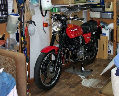
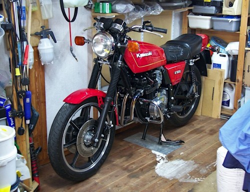
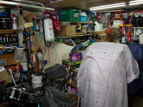
Put the Z500 to bed for the winter here it is in the winter corner and now full covered. Bandit sitting next to it and the GS125 at the front ready for use